0 Preface
China is a country with scarce resources, but people do not realize this in their daily lives. Taking indoor lighting as an example, manual switches are used in many public places, and there is often a phenomenon that the lights are not turned off in time, which causes waste of energy and shortens the service life of the lamps. In response to this phenomenon, it is necessary to study an intelligent lighting control system. The system uses intelligent sensors to sense outdoor brightness to automatically adjust the light to maintain a constant indoor illuminance, which can not only provide the best indoor lighting environment, but also achieve energy-saving effects.
LED is called the fourth generation of green light source. The light-emitting device of LED is a cold light source, which has the characteristics of energy saving, environmental protection, long life and small size.
LED light has good monochromaticity, narrow spectrum, no need to filter, and can directly emit colored visible light. Under the same lighting conditions, the power consumption of LED lamps is one-tenth of incandescent lamps and one-half of fluorescent lamps, which is the future development trend of lighting.
1 Intelligent control scheme design
The system uses a photoresistor to detect the environmental brightness, a pyroelectric infrared sensor to detect trace infrared rays radiated by the human body, and a temperature detection module to detect the temperature of the LED. The signal detected by the sensor is pre-processed and transmitted to the single-chip computer, which controls the switching and brightness of the LED lamp after processing by the single-chip computer . The system block diagram is shown in Figure 1.

2 Hardware design
2. 1 pyroelectric infrared detection module
The pyroelectric infrared detection module does not need to be equipped with an infrared emission source, and can directly receive a small amount of infrared radiation radiated by the human body and convert it into a corresponding electrical signal output. In order to improve the sensitivity of the PIR sensor to infrared rays, a matching Fresnel lens is added in front of the sensor.
The pyroelectric infrared detection module is composed of Fresnel lens, pyroelectric infrared sensor (PIR), control circuit and drive circuit. The block diagram of the pyroelectric infrared detection module is shown in Figure 2.

The human body has a constant body temperature, generally at 37 ℃, and emits infrared rays with a specific wavelength of about 10 μm. The infrared light radiated by the human body is collected on the two detection elements of the PIR through the Fresnel lens. When the human body moves, the infrared radiation intensity changes, the charge intensity on the surface of the detection element changes, and the signal output is amplified by the internal field effect tube. .
The pyroelectric infrared detection module is processed by a special pyroelectric control integrated circuit, here using BISS0001 type integrated circuit.
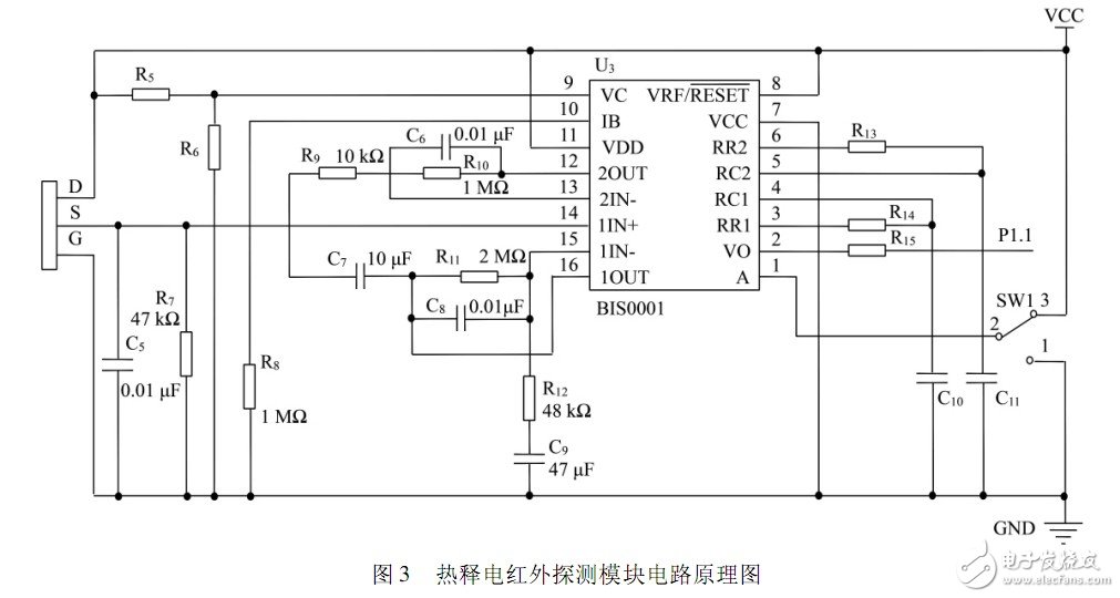
BISS0001 integrated circuits have built-in independent high input impedance operational amplifiers, which can be matched with various sensors for infrared signal preprocessing. The chip contains unit circuits such as voltage comparator, state controller, delay circuit timer, blocking time timer, and reference voltage source. The circuit is shown in Figure 3.
2. 2 ambient brightness detection module
Photoresistor is a special resistor made by semiconductor photoconductor effect, which is very sensitive to light. It is used here to detect the ambient brightness. Its resistance value can change with the change of external light intensity. It is in a high-resistance state when it is not exposed to light; when it is exposed to light, its resistance decreases rapidly.
R6 in Figure 3 is a photoresistor. If the environment is brighter, the resistance value of R6 will be reduced, so that the input of pin 9 is kept low, thus blocking the trigger signal VCC.SW1 is the working mode selection switch. When SW1 and 3 are When connected, the chip is in the repeatable trigger working mode; when SW1 and terminal 1 are connected, the chip is in the non-repetitive trigger working mode.
An ADSL filter separates the analogue voice-frequency signals from the ADSL (broadband) data signals(Broadband being defined as data transfer greater than 128KBPS.)
If ADSL filter/splitters are not used, the ADSL data signals are heard as "noise" on any equipment connected to the "normal" telephone-line. Apart from being annoying during a telephone conversation, there is the possibility that the additional ADSL signals may cause problems with alarm-units (etc) that may be connected across the line.
This ADSL-interference is illustrated in the diagram below that shows how the unfiltered ADSL data signals appear across the "standard" telephone equipment.
We can supply you ADSL Splitter,ADSL Filter, ADSL Modem Splitter,Telephone Splitter,adsl2+ splitter,adsl filter splitter, ,adsl dsl filter splitter,adsl in line splitter,adsl filter and splitter, ,rj11 splitter, broadband splitter, mdf splitter, adsl modem filter with a good quality and best price.

ADSL Splitter, 2Wire DSL Filter, ADSL Modem Splitter, Telephone Splitter, ADSL Splitter Filter,VDSL Splitter
NINGBO YULIANG TELECOM MUNICATIONS EQUIPMENT CO.,LTD. , https://www.yltelecom.com