introduction
LED dot matrix electronic display is a large display system integrating microelectronics technology, computer technology and information processing technology. It is an ideal choice for many display media and outdoor work displays due to its bright colors, wide dynamic range, high brightness, long life and stable operation. It can also be widely used in many industries such as military, station, hotel, sports, news, finance, securities, advertising and transportation.
At present, most LED dot matrix display systems have their own fonts. The implementation of its display and dynamic effects (mainly the scrolling of the display content) mainly relies on the hardware scan driver. Although this method is convenient, the display can only be performed according to the pre-design. In fact, it often encounters some dynamic display of special requirements, such as the up and down movement of the indicator arrow in the elevator running, the bar display of the amplitude of some smart meters, and the trademark display of the manufacturer in the advertisement. At this time, the general display system is difficult to meet the requirements.
In addition, due to the limitations of the memory itself, its special characters or patterns are often difficult to display, and the display content cannot be changed at will. This paper proposes a communication method of LED display system controlled by PC and single chip microcomputer. The method can control the display content (including Chinese characters and special icons) in real time, thereby realizing various dynamic display effects such as flashing, scrolling, and typing. The method can also adjust the speed of the dynamic display, and the user can also preview the display effect on the PC, and the display content can be modified in real time. In addition, remote control of the display system is also possible via the standard RS232/485 conversion module.
2, system hardware design
The main hardware design of this system is the display control part of the lower computer. The interface between the host computer (PC) and the display control part of the MCU is the standard RS232 communication mode. If you need to achieve remote monitoring, you only need to add RS232/485 conversion module. This part has mature circuit design, so it will not be described in detail.
The specific LED display control circuit is shown in Figure 1. The whole circuit is composed of a single chip microcomputer 89C52, a dot matrix data memory 6264, a column driving circuit ULN2803, a row driving circuit TIP122, a shift register 4094, and an auxiliary circuit. The electronic screen designed by the circuit can display 10 Chinese characters, and requires 40 8×8 LED dot matrix modules to form a rectangular matrix of 16×160. Since the AT89C52 has only 8k storage space, and the displayed content is controlled by the PC, it is impossible to pre-set the content to be displayed in the single-chip microcomputer, and the dot matrix data to be displayed can be instantly displayed by the PC. It is passed to the microcontroller and stored in the buffer 6264.
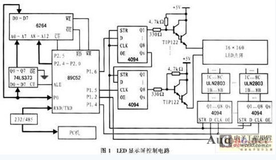
The display of this circuit uses progressive scanning. When working, the MCU takes out the 20-byte dot matrix data that needs to be displayed in the first line from the buffer, and then serially inputs the data into the column shift register by the column data input terminal P1.2. The order is the reverse of the order in which the content is displayed. Then set the dot strobe P1.3 to 1, that is, the D of the shift register is high, and the STR is enabled (all 409 pins of the 4094 are connected to +5V level), thereby making the column shift register The data in is simultaneously output in parallel to gate the line. After a delay, the display of the next row of dot matrix data is performed. It should be noted that only one line of data can be strobed at a time, that is, the display of Chinese characters or characters is realized by continuous progressive scanning.
3, display and control design
In the PC-controlled multi-microcontroller display system designed by the author, the main functions realized by the PC include the selection of the display subsystem of the single-chip microcomputer, the display mode selection (including static, flashing, scrolling, typing, etc.), the scroll direction selection (including upper and lower Scrolling and scrolling left and right), dynamic display speed adjustment (ie text flashing frequency, scrolling speed, typing display speed, etc.), display content input and display preview. The MCU generally uses the RS232/485 serial receiving PC to display the display. The timer interrupt mode is used for line scanning. Each time the interrupt is displayed, the timing interrupt time is 1.25ms, so the refresh rate of the whole screen is 50Hz, so there is no flicker. .
The method of realizing the dynamic display speed adjustment is usually to change the interrupt time of the timer, but when the display speed is very slow, the method tends to lower the refresh rate of the entire screen, thereby causing the display content to flicker. Therefore, this design uses a "soft timing" method, in which a variable is named in the program as a "soft timer" to set the time interval between two dynamic displays. When counting the timer interrupt call, if the number of calls reaches the set value, the display content is changed. In order to ensure normal display, the setting value of "soft timer" must be greater than the full screen display period. Since the display shows 1.25ms per line and the display period of the whole screen is 20ms, the setting of the soft timer can be set to be greater than 30ms in consideration of the margin. This cycle counts to achieve dynamic display. The setting value of “soft timer†can be changed by the PC of the host computer, which can realize the speed adjustment of the dynamic display of the LED, and maintain the smooth and flicker-free display content.
3.1 MCU dynamic display control
The four display modes of static, flashing, scrolling and typing mentioned above are actually different methods for the line scan processing of the single-chip timer interrupt program. The following will explain how to implement these four display modes.
The static display only needs to transfer the corresponding line of display data from the display buffer in the timer interrupt handler, and then select the line to realize the display of the line. In this cycle, the entire content can be displayed. The flashing display is similar to this. The difference is that the timing of a "soft timer" is to be separated. When the line is scanned, the D-bit of the row shift register is all 0, so that the entire screen is not displayed to ensure The black screen time is equal to the display time, so that the flashing display of Chinese characters or icons is realized.
The scroll display requires that the content to be displayed be moved to a specified direction (here, from right to left as an example) at a certain time so that the display can display more content. To do this, it is necessary to change the content of the display buffer before moving the display next time, thereby completing the shift operation of the corresponding dot data. The specific method of operation is:
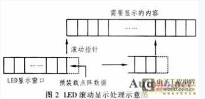
Set a display buffer (as shown in Figure 2), this area should include two parts: one part is used to save the 10 Chinese character dot matrix data displayed on the current LED display; the other part is the dot matrix data preloading area, To save the dot matrix data of a Chinese character that is about to enter the LED display. The scroll pointer always points to the rightmost origin of the display. When the scroll pointer moves to the first address of the first Chinese character of the dot matrix data storage area to be displayed, the display buffer LED display area is blank, and the preloaded area has saved the dot matrix data of the first Chinese character to be displayed. . When scroll display is required, the corresponding row dot matrix data of the display buffer is shifted to the left by one bit in each row scan interrupt handler of the next scan cycle, and the content of the display buffer is changed. (It is important to note that this operation can be completed within 1.25ms of interrupt time. Here the 89C52 uses a 22MHz crystal, which has been shown to work.) Thus, after one scan cycle, the entire Chinese character will be shifted to the left by one column, and the contents of the display buffer will also be changed at the same time. Since the preloading area holds one Chinese character dot matrix data, that is, a 16×16 dot matrix, the content of the current display buffer can only be moved by 16 columns. When the next scroll arrives, the scroll pointer will move to the first address of the next Chinese character in the dot matrix data storage area, and the dot matrix data of the Chinese character will be stored in the preload area. Then repeat the above operations to achieve scroll display. The display of special characters or graphics is similar, and will not be described here.
The typing display requires that the Chinese characters appear one by one in the order from left to right on the display screen, just like the effect of typing. The following methods can be used in design: firstly, the display buffer corresponding to the LED display is completely cleared, that is, the LED display is blank, and then the dynamic display time set by a “soft timer†is set, and the display buffer sequentially adds a Chinese character point. The data is scanned and displayed, so that the effect of typing can be achieved.
3.2 PC control program
a. Implementation of communication functions
In the Windows environment, the communication between the PC and the microcontroller can be realized by using the communication API function of Windows or by using the standard communication functions _inp and _outp of VC++ (or other languages). However, the above two methods are cumbersome, and it is very convenient to implement the ActiveX control MSComm32. The control simplifies the programming of the serial port operation by means of events, and can set the data transmission and reception of serial communication, and also can set the information format and protocol of the serial port status and serial communication. Its initialization procedure is as follows:

Under normal circumstances, the PC should communicate with multiple MCU 89C51 systems in master-slave mode. In order to distinguish each MCU system, the 89C51 can use the serial port working mode 3, that is, the 11-bit asynchronous receiving/transmitting mode. The valid data of this mode is 9 bits. The ninth bit is a flag bit of the address/data information, and its role is to enable the slave to judge whether the transmitted data is an address, thereby implementing multi-machine operation. But now because of the MSCOMM control used to achieve communication between the PC and the microcontroller, this is a standard 10-bit serial communication method, that is, 8-bit standard data bits and 1 bit of the start and stop bits of the data. . Therefore, the format of the two does not match, so it is difficult to use the above scheme. Therefore, it can be considered to set the serial port of the single chip to work mode 1, that is, to change to the 10-bit asynchronous receiving/sending mode. The communication flow is as follows: first send the communication start flag, then send the address of the single-chip system to be operated, and then send the display work command. Word, the command consists of 2 bytes, the first byte is used to set the display mode and scroll direction, and the last byte is used to set the display speed. Further down is the dot matrix data that conveys the display content, and finally the data is verified. The communication protocol is very simple, and can better solve the above problems, thereby realizing master-slave communication and display control between the PC and the multi-chip microcomputer .