If you are a designer responsible for migrating the USB ports in your system to the latest USB standards and USB type-c connectors, you may have considered some things.
ESD protectionFirst, like all systems that expose the connector to the user externally, your system needs to have International Electrotechnical Commission (IEC) 61000-4-2 Electrostatic Discharge (ESD) protection. In addition, you need to protect more signal pins than previous USB Type-A or USB Micro-B connectors. The 24-pin USB type-c connector (Figure 1) requires ESD protection for two differential pairs (D + / D-) for USB 2.0 data; four differential pairs for up to 20Gbps (TX / RX The ultra-high speed data bus, sideband use (SBU) pin, and two configuration channel (CC) pins are used to detect cable direction.

Figure 1: Full-featured USB type-c plug-in pinout
Overvoltage protectionSecond, with the introduction of up to 100 W of USB power output (PD), the VBUS pin can now carry voltage levels up to 20V. If VBUS is shorted to an adjacent CC, it may cause serious damage to the downstream USB type-c controller or SBU pin. To prevent hardware system failure, the connector requires overvoltage protection in addition to ESD protection.
Considering the risk of overvoltage protection (OVP) events, the ESD diode itself must also be able to withstand 20 VDC. Many of the current high voltage protection options are clamped when the voltage is too high, protecting the downstream controller during IEC ESD trigger events. Now consider the impact on the system from a short circuit to a VBUS event when the cable is present at the connector (or when the cable is not present). When the cable causes ringing that may exceed 40V, the solution must protect the system. In short, rugged USB Type-C connector protection requires not only standard ESD diodes, but also higher voltage, DC withstand transient voltage suppressor (TVS) diodes.
System protection is required for OVP and IEC ESD protected connectors, but a complete USB Type-C port protection solution should conform the system to the new USB standard specifications. For example, if the system utilizes new USB Type-C features (such as support for ultra-high-speed communication), the USB Type-C specification requires VCONN support on the CC line to power the active cable. In order for the OVP solution to operate on a CC line, a 5.5VDC power rail must be supported. Port protection must also have low on-resistance (RON) to ensure that the total voltage drop across the power rail does not exceed the USB specification.
If the system is battery powered and relies on a Type-C connector as the power source, the solution must protect the CC line from overvoltage conditions, even when the battery is exhausted.
These and other complex scenarios yield a robust solution to protect USB Type-C ports, not as straightforward as adding ESD protection diodes and OVP FETs. The OVP FET needs to withstand the clamping voltage given by the high voltage discrete TVS diode, which makes the FET costly and bulky with low RON requirements. This makes the discrete implementation complex and costly, while consuming a large footprint around the compact size of the USB Type-C connector.
Finally, think about it, "My system is simple because it doesn't support higher wattage (> 15W) PD functionality, fully compliant with <15W PD specifications," and noticed that most of the USB Types on the market have been found. -C cables and adapters do not meet the standard, while other types may fail (Figure 2). Even in a 5V system, there is a risk that a short circuit of up to 20V may occur to VBUS before negotiating with the PD of the controller. If this is the case, not only will the system be damaged, but the product reputation will also be impaired.
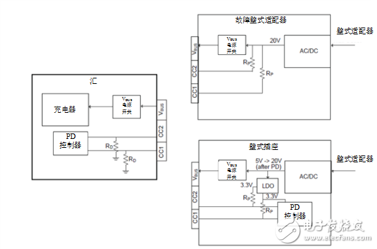
Figure 2: CC pin exposure for conventional and faulty wall adapters
For more information on design considerations for USB Type-C port protection, read the TI white paper: "Circuit Protection USB Type-CTM." Devices that integrate TI's USB Type-C port protector family, such as the TPD8S300 or TPD6S300, address the complexities of migrating USB ports to new USB Type-C connectors.
other information· Download the TPD8S300 or TPD6S300 data sheet.
· Read this Analog Wire blog post "Understanding the challenges to avoid when implementing USB Type-CTM protection."
· Start designing with the TPD8S300 evaluation module now
• Check the TPD1E01B04 single-channel ESD protection diode for overspeed data lines.
· Learn more about the TUSB1046-DCI and TUSB546-DCI USB Type-C Alternate Mode Linear Adapters.
Subminiature Sealed Micro Switch
Features
â—† Designed For Water and Dust Tight(IP67)
â—† Small Compact Sizeâ—† UL&ENEC&CQC Safety Approvals
â—† Long life & high reliability
â—† Variety of Levers
â—† Wide Range of wiring Terminals
â—† Wide used in Automotive Electronics,Appliance and Industrial Control etc.
â—† Customized Designs
Safety Micro Switch,Central Locking Switch,Sealed Waterproof Micro Switch,Subminiature Sealed Micro Switch
Ningbo Jialin Electronics Co.,Ltd , https://www.donghai-switch.com