The rapid development of digital electronic information technology has greatly promoted the manufacturing industry around the world, making the design of various devices in the manufacturing industry more and more electronic, digital, and networked. The ECCT product is a product launched by Emerson CT. Specialized electromechanical device PLC controller with CAN bus protocol, which is specially used in the textile industry, it not only satisfies the basic I/O process requirements of textile, but also integrates the CAN bus protocol perfectly, making it easy for users to put the system Various devices are connected by CAN protocol. This paper introduces the application of CAN bus function in Emerson CT PLC.
This article refers to the address: http://
Introduction to CAN bus basics
The CAN bus (CONTROLLER AREA NETWORK) is first proposed by the German company BOSCH. The CAN bus is a bus widely used in the industry. Its characteristics are summarized as follows:
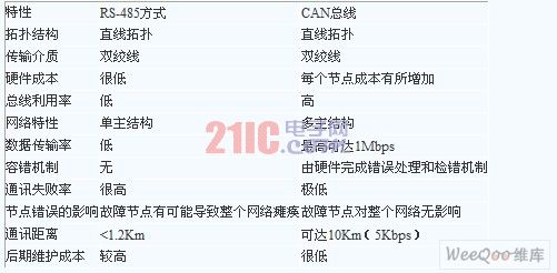
1) The CAN controller works in a multi-master mode, and each node in the network can compete to send data to the bus according to the bus access priority (depending on the message identifier) ​​using a lossless structure of bit-by-bit arbitration. The use of RS-485 can only constitute a master-slave structure system, and the communication method can only be carried out in the manner of polling by the primary station, and the real-time performance and reliability of the system are poor.
2) The CAN protocol abolishes the traditional station address coding and instead encodes the communication data. The advantage is that the number of nodes in the network can be theoretically unrestricted. Adding or reducing equipment does not affect the system's work. . At the same time, different nodes can receive the same data at the same time. These characteristics make the data communication between the nodes of the network formed by the CAN bus real-time, and easily form a redundant structure, thereby improving the reliability of the system and the flexibility of the system.
3) The CAN bus is connected to the physical bus through the two output terminals CANH and CANL of the CAN controller interface chip, and the state of the CANH terminal can only be a high level or a floating state, and the CANL terminal can only be a low level or a floating state. This ensures that there will be no similar phenomenon when the system has an error in the RS-485 network, which will cause multiple nodes to send data to the bus at the same time, causing the bus to short-circuit and damage some nodes. Moreover, the CAN node has an automatic shutdown output function in case of a serious error, so that the operation of other nodes on the bus is not affected, thereby ensuring that there is no problem in the network, and the bus is in a "deadlock" due to a problem with an individual node. status.
4) The perfect communication protocol of CAN can be realized by CAN controller chip and its interface chip, which greatly reduces the difficulty of user system development and shortens the development cycle. These are unmatched by RS-485 only with electrical protocol. .
5) Compared with other fieldbuses, the maximum speed of CAN bus communication is up to 1MBPS, the transmission rate is 5KBPS, the twisted pair is used, the transmission distance is up to 10KM, and the data transmission reliability is high; the CAN bus has high communication speed. An easy-to-implement, cost-effective and many other features that have formed an international standard fieldbus. These are also important reasons why CAN bus is used in many fields and has strong market competitiveness.
The difference between CAN bus and RS485 mode:
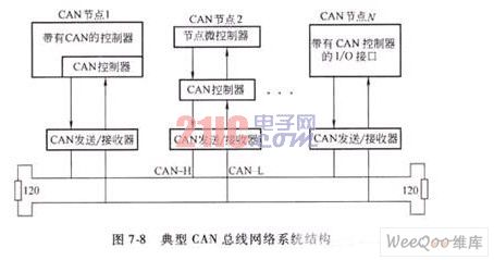
CAN bus system structure: Each node of CAN bus needs to have CAN protocol control chip and appropriate interface circuit. The nodes are connected by bus through twisted pair shielded wires. The first and last nodes need to be connected with 120R matching resistors. 1MBPS, the lower the transmission rate, the farther the transmission distance. The system structure is as follows:
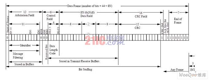
CAN protocol message format: CAN protocol supports two message formats CAN2.0A and CAN2.0B; CAN2.0A is the standard format, and CAN2.0B is the extended format; the formats are as follows:
The structure diagram of CAN2.0A protocol message is as follows
The structure of the CAN2.0B protocol message is as follows

The only difference between the standard format and the extended format is that the identifier (ID) length is different, the standard format is 11 bits (ID10-ID0), and the extended format is 29 bits (ID10-ID0, EID17-EID0).
In the standard format and the extended format, the start bit of the message is called the start of frame (SOF), the start of the frame start flag data frame or the start of the remote frame, consisting of a single "dominant" bit (0). It is automatically completed by the control chip and does not need to be reflected in the program by the user.
Then there is an arbitration field consisting of an 11-bit identifier (ID10-ID0) (extended format is 29 bits (ID10-ID0, EID17-EID0)) and a remote transmission request bit (RTR). The RTR bit indicates whether it is a data frame or a request frame, and there is no data byte in the request frame.
The control field includes an identifier extension bit (IDE) indicating whether it is a standard format or an extended format. It also includes a reserved bit (RBO) for future expansion. Its last four bits are used to indicate the length of the data in the data field (the size is the binary data consisting of DLC3-DLC0). The data field ranges from 0 to 8 bytes (DATA FIELD), followed by a Cyclic Redundancy Check (CRC) that detects data errors.
The acknowledge field (ACK) includes an acknowledge bit and a reply separator. The two bits transmitted by the transmitting station are recessive levels (logic 1), at which point the receiving station that correctly receives the message transmits the master level (logic 0) to overwrite it. In this way, the transmitting station can ensure that at least one station in the network can correctly receive the message.
The end of the message is marked by the end of the frame. There is a short interval between two adjacent messages. If there is no station for bus access, the bus will be idle.
Emerson CT PLC integrated CAN bus function introduction
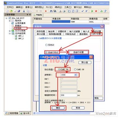
ECCT's CAN communication function supports CAN2.0A protocol and CAN2.0B protocol. The communication baud rate setting range is 5-100KBPS, which can be set by Emerson CT PLC programming software CONTROLSTAR FOR ECCT. The specific steps are as follows:
1) Basic settings: Double-click “System Block†in the Project Manager, select “CAN Port Settings†in the pop-up window, select “Free Protocol†in “CAN Port Parameter Settingsâ€, and then click “Free Port Settingsâ€. "The button. In the pop-up window, select the protocol type "2.0A" or "2.0B", then pull down and select "Baud Rate" and finally click "OK" to download the system block to the PLC.
2) Data transmission: The instruction CANXMT is used, and the correspondence between them is depicted by taking the CAN2.0A protocol as an example.

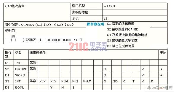
3) Data reception: Use the CANRCV instruction (the parameters are as follows) or use the CAN to receive the interrupt function. I recommend it easier to use interrupts for the first time user. For details, please refer to the following example program.
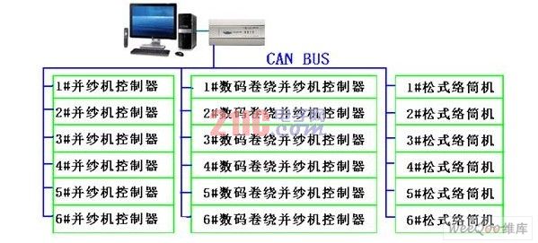
According to the CAN bus function integrated by ECCT, the author has successfully applied in textile machinery. The following is the following: The overall structure of the CAN system is as follows:
The specific process of this system is not introduced. Only the application of CAN communication part is introduced here.
The instructions for using the program are as follows:
1. First set the CAN communication port in the "system block" as required.
2. Data transmission part: The program to be written by sending 4 words of data "16#1122, 16#3344, 16#6789, 16#1234" to the address of ID 5 is as follows:
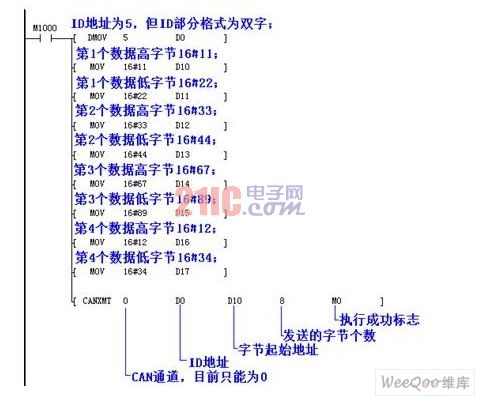
Among them should be noted that: 1) CANXMT executes the instruction on the rising edge, M1000 is the instruction execution condition, when it changes OFF->ON, the CANXMT instruction is executed; 2) Write the address of the assignment before using the CANXMT instruction 3) The transmission data only takes the lower 8 bits of the D component; 4) The CAN frame with no CANID and the same data on the network appears at the same time; 5) The ID remains 0. 6) The verification part of the CAN program is automatically completed by hardware. User programs do not need to participate.
3. Data receiving part: This part takes the example of receiving data by using the interrupt method, and is divided into two parts:
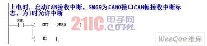
1) First set the CAN interrupt enable in the main program.
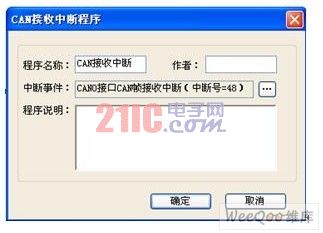
2) Set the interrupt program property, select its interrupt event as 48 (that is, CAN receive interrupt), and then write the program to transfer the received data to the required address. Note that the ID address is a double word structure, and SD282-290 is data in turn. The high and low bytes, pass them to the corresponding data registers and merge to get the complete data.

Summary: Since the CAN protocol format is relatively simple, and a considerable part of the work is done by the CAN control chip hardware, the programming procedure is relatively simple and easy to implement. After the textile system adopts the CAN communication method, the speed is greatly improved and the system is more stable and is subject to users. Affirmation.
Utp Connector,8P4C Connector,8P8C Crystal Head Connector,Rj45 Crystal Head Connector
Dongguan Fangbei Electronic Co.,Ltd , http://www.connectorfb.com