Abstract: A GPS receiver is designed for economical and practical use. The receiver uses TI's TMS320F2812 chip as the core processor, and the GPS-OEM board is redeveloped twice, and the detailed hardware and software design ideas and implementation schemes are given. The test results show that under the condition of good weather conditions, the positioning accuracy of single machine is less than 1 m, which can meet the measurement accuracy requirements of most geophysical planes.
Keywords: geophysical exploration and measurement; GPS-OEM; TMS320F2812; GPS receiver
0 Introduction In the field of geophysical exploration, geophysical field measurements are carried out while point and elevation measurements are required. Compared with the conventional measurement technology, the GPS positioning technology has the advantages of no need to look at the observation station, fast speed, and less investment by the measurement group. It has become the first choice for object detection.
In geophysical survey measurements, planar positioning accuracy is required to be less than 3 m. At present, the accuracy of low-cost GPS receivers on the market cannot be guaranteed; high-precision GPS receivers can meet the accuracy requirements, but they are expensive. In order to meet the geophysical exploration geodetic needs, geophysical prospectors often have to use high-precision GPS receivers, which obviously increases the cost of geodetic work. In view of the current development status of GPS receivers, this paper aims to develop a special GPS receiver, which requires moderate price, real-time positioning, and single-machine positioning accuracy of 1 to 3 m in a short time, meeting most geophysical exploration geodesy. Precision requirements.
The digital signal processor DSP has high computing speed, high digital signal processing capability and high reliability, and is very suitable for GPS real-time signal processing. The use of GPS-OEM for secondary development, design of corresponding interface software, adaptation of display, keyboard and other user terminals and control processors to form a GPS integrated receiver has become a development trend. Through research, a GPS-OEM board is selected, and when used in conjunction with a butterfly receiving antenna, the positioning accuracy of a single machine can reach about 1 m, which provides a basic basis for further design.
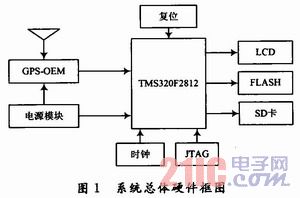
1 system hardware design The receiver consists of GPS data receiving unit, core processing unit, and storage and display unit. Among them, the GPS data receiving part adopts the selected GPS-OEM board design, the core processing unit adopts TI's DSP, and the interface part mainly consists of the conversion chip and corresponding software. The overall hardware framework of the designed system is shown in Figure 1.
This article refers to the address: http://
1.1 GPS data receiving module design Currently there are many types of GPS-OEM modules in the market, according to:
(1) The positioning accuracy that the design system can achieve;
(2) The communication mode and coverage of the data link;
(3) Select the appropriate OEM module by factors such as performance price ratio.
After weighing and comparing, the design adopts a GPS-OEM module Crescent-HC12A officially launched by Hezhong Shuangzhuang in 2006. The module is a single-frequency 12-channel receiver produced by Hezhong Shuangzhuang Company. It adopts the latest ASIC chip and patent software algorithms such as Coast. It also has 20Hz raw data, positioning data update rate, beacon receiving function, and differential base station/ Mobile stations, L-Dif, E-Dif, 1 pps/Event Marker and other functions, with a single positioning error of less than 2.5 m (2DRMS), represents the latest technology trends in the current GPS industry.
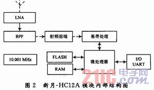
The new moon-HC12A module is mainly composed of low noise downconverter, signal channel, microprocessor, memory, etc. The internal structure is shown in Figure 2.
In addition, according to the antenna supply voltage, signal-to-noise ratio (about 1.5 dB noise figure) and gain (about 28 dB gain), a right-handed polarized ceramic dielectric antenna is selected, and the GPS signal receiving antenna has been observed at the same time. More GPS satellites, fast positioning features.
1.2 DSP core processing module is designed to meet the requirements of fast positioning, high reliability and real-time performance of the receiver system. The DSP chip is selected as the core of the central processing unit, and the data structure of the demand data according to the central processing unit is The effective number required for processing is up to 11 bits), taking into account the computing speed of the DSP chip, the accuracy of the operation, the hardware resources of the DSP chip and the development tools, power consumption and price.
TI's TMS320F2812 chip was selected as the main processor, mainly based on the following considerations:
(1) Its high frequency, clock frequency up to 150 MHz, can meet the needs of the system;
(2) The large-capacity on-chip FLASH that it has can facilitate system implementation and reduce costs;
(3) It has more general-purpose I/O ports that can be flexibly configured, and can be easily interfaced with other devices;
(4) The TMS320F2812 chip system uses high-performance static CMOS technology and consumes very low power.
1.3 Storage, Display and Control Unit In order to provide the user with positioning information in real time, the LCD design and SD card memory are used in this design as the man-machine dialogue window. It can output positioning information in real time and quickly, and design a simple and convenient and friendly man-machine interface through software programming. The measurement can be carried out according to a simple operation prompt. In addition, you can also store the necessary data in the SD card storage internal device for subsequent query.
2 System software design The software program designed in this paper uses C language and assembly language for mixed programming, compiling and debugging the subprogram of each function module. The main part of the program design includes: the main program part; the receiving subroutine; the data processing subroutine; and the storage part subroutine. The specific software flow designed is shown in Figure 3.
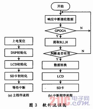
(1) Main program part: Mainly complete CPU initialization of DSP, establish interrupt vector table, initialize SD card, initialize to OEM board, etc., and call each subroutine.
(2) Receive subroutine: Make the program point to the first address of the receive data buffer, and let the DSP be in the read receive state. When the new moon-HC12A OEM board receives a frame signal, it will receive the interrupt from the serial port and send the interrupt signal to the interrupt controller of the DSP. After it determines the source of the interrupt, the DSP will find the corresponding interrupt service program. Entrance address. The interrupted mode is used to receive the data sent by the OEM board, and the received character is always the valid start character of one frame of data. After the feature word "$GPG-GA" is judged, the information content is received, and if it is met, it is received; otherwise, it is discarded. Re-judgment. When received, received
(3) Data processing subroutine: first buffer the received data, extract and convert the received valid frame data, separate the data with "," as the mark, extract and interpret the first, second, fourth, and nineth. With a comma, you can extract the corresponding time, longitude, latitude, height and other information. The obtained latitude and longitude information is ddmm. The mmmmm format, which is a character type that needs to be converted to decimal. In addition, due to the different time standards, it is necessary to convert the extracted time information in order to obtain Beijing time. If coordinate transformation is required, the coordinate transformation subroutine should be called. The useful information is sent to the LCD display after processing.
(4) Storage part subroutine: For the received data, after the extraction process, the data is stored in the cache. When the cache is full of 512 b, it is written into the SD card for later processing.
3 test results analysis
3.1 Static test scheme and analysis The GPS antenna was placed on the roof with a tripod. Four antennas were tested at different positions. The data acquisition time of all static points lasted for 5 min (300 data points). A file of location data corresponding to each time period. The latitude and longitude information of the standard points is extracted, and the position distribution is obtained as shown in FIG. 4.
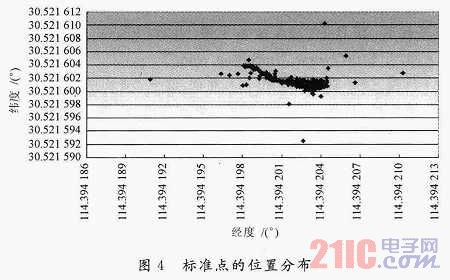
It can be clearly seen from Fig. 4 that although there are some outliers, the data density is relatively high. After calculation, the longitude direction is mainly concentrated at 114.394 196 ° ~ 114.394 205 °, the difference is about O. 000 009° (O.863 2 m); the latitude direction is mainly concentrated at 30.521 599 ° ~ 30.521 604 °, the difference is only about O. 000 005° (0.554 7 m). From the above data analysis results, in the case of better weather conditions, the plane error of single point positioning is less than 1 m.
CEP analysis: In order to test the index (single-machine positioning: less than 2.5 m (2DRMS)) calibrated by the manufacturer, the measured data of the four points collected in the weather is fine, and the method of calculating the circular probability error is used. An analysis was performed; the test time for each point was 5 min, each obtaining 300 data points. Calculate the radius error radius of the circle, and use Matlab software to program the graph to get the circular probability radius graph. As shown in Figure 5, only one graph is listed.
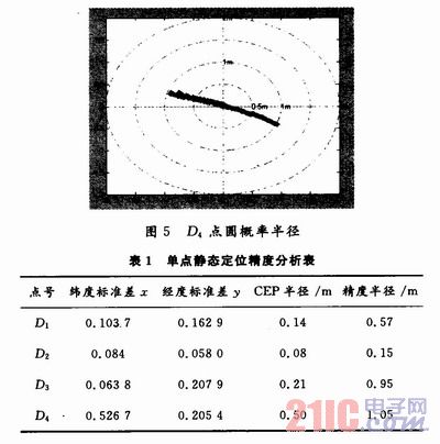
It can be seen from Fig. 5 that the measured points are all included in a circle with a radius of 1.05 m. The experimental data of the specific calculations of each point are shown in Table 1.
As can be seen from Table 1, the maximum accuracy radius of the measured data is 1.05 m. The maximum value of the circular probability error radius (CEP) at each point is o. 5 m, these data are less than the receiver's calibration position accuracy of 1.042 m (CEP) (converted from 2.5 m (2DRMS)).
3.2 Dynamic test plan and analysis This experiment was designed to test the measurement accuracy in motion. The experimental site was on the west playground, and it was returned to the original point after one week of the first runway and the third runway of the pre-scenery, and four experiments were carried out respectively. Maintain a constant speed during the bypass. After extracting and transforming the collected data, the data is simulated by Matlab software, and the measured latitude and longitude is converted into a distance unit, and the trajectory of the four experiments is shown in Fig. 6.
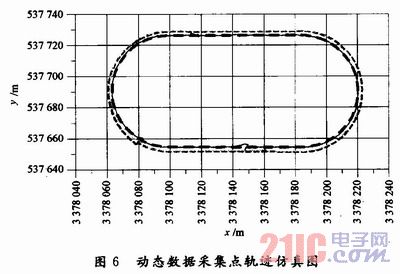
In Figure 6, the inner two turns are on the first runway line, and the outer two turns are the trajectory on the third runway line. Each runway is 1.2 m wide and the distance between the two lines is 2.4 m. . Although there are errors in the trajectory points and linear trajectories obtained during walking, it is generally ideal. The maximum deviation distance of the experimental trajectories is within 1 m, which is basically consistent with the static positioning accuracy.
The main reason for analyzing the error in the analysis of the maximum deviation is that the antenna is not always maintained on a horizontal plane during walking, and it is not guaranteed that the walking route is completely coincident. In general, the positioning trajectory map can better reflect the actual shape. It shows that the dynamic positioning performance of the GPS module is still relatively good and can be used for more accurate real-time navigation.
The comprehensive static and dynamic test results show that the maximum probability error radius (CEP) of the new moon-HC12AGPS module is 0.763 9m, which is less than its calibration position accuracy of 1.042m (CEP), indicating that the accuracy reference value provided by the manufacturer is reliable.
The accuracy radius (100% point) of the obtained single point is about 2m, which is less than the manufacturer's (2.5m), which indicates that the module can meet the plane measurement accuracy requirements of the object detection network in most cases, indicating that the system design scheme is feasible.
4 Conclusion In this paper, through the research and design of the entire receiver system, the main conclusions are as follows:
(1) The selected GPS-OEM positioning accuracy can meet the design requirements. The stand-alone static test results using the right-handed polarized ceramic dielectric antenna show that the single-point positioning accuracy is less than 1m, and the maximum deviation of the navigation of the receiver is also about 1 m by 4 dynamic tests, which can satisfy most of the Plane measurement accuracy requirements for geophysical exploration.
(2) The overall idea of ​​designing a GPS receiver system is correct. It is correct to use the low-end GPS-OEM to design a GPS receiver with high accuracy and moderate price. It realizes the development of high-precision GPS receiver with low-end GPS-OEM and better receiving antenna. Imagine and provide a reference for subsequent designers.
(3) The proposed overall design is feasible. It is feasible to select GPS chip and GPS-OEM board to develop GPS receiver, which can meet the functional requirements of real-time positioning; the selected TMS320-F2812 DSP chip can meet the requirements of real-time. The DSP module circuit designed in it can meet the system requirements.
Water-Cooled Capacitor is supercapacitor is a capacitor with a capacity of thousands of farads.According to the principle of capacitor, capacitance depends on the distance between the electrode and electrode surface area, in order to get such a large capacitance, as far as possible to narrow the distance between the super capacitor electrode, electrode surface area increased, therefore, through the theory of electric double layer and porous activated carbon electrode.
Water-Cooled Capacitor,Water-Cooled Power Capacitor,Water-Cooled Electric Heat Capacitor,Water-Cooled Electric Heating Capacitor
YANGZHOU POSITIONING TECH CO., LTD , http://www.yzpstcc.com