Abstract: In view of the demand for automatic dimming of automotive HID headlights, this paper designs a set of headlamp automatic dimming system based on LIN bus. The basic design scheme, hardware composition and basic design of software design are introduced, and the basic framework of software programming is given. Keywords: headlights; automatic dimming; LIN bus; stepper motor control Introduction HID is the abbreviation of High Intensity Discharge, also known as heavy metal or Xenon headlights. Compared with traditional halogen bulbs, HID has the advantages of high brightness, long life and power saving.
It is precisely because HID has the characteristics of high brightness. If the height of the illumination is improperly adjusted during use, it will cause strong glare to the driver who comes to the car when the car is in use, posing a safety hazard. In order to regulate the market for HID headlamps, the United Nations Economic Commission for Europe clearly states in ECE-R48 that vehicles equipped with HID headlamps must be equipped with a system that automatically adjusts their exposure height. It can be called a headlamp level automatic dimming system. When the system works, the projection pitch angle of the HID headlights is automatically adjusted according to the change of the vehicle load to ensure that the projection height is within a suitable range, which not only achieves good lighting effects, but also does not dazzle the driver of the oncoming vehicle.
The overall scheme design of the system is shown in Figure 1. The system can be divided into three parts, namely the vehicle height sensor, the central control unit and the drive execution unit. The system operation is as follows: the main MCU (MC68HC908GZ60) of the system collects the signals of the front and rear axle height sensors of the vehicle body, and after the operation, sends a control signal to the horizontal dimming stepping motor of the left and right headlights respectively, indicating that the motor rotates to the designated position, and completes Automatic dimming. 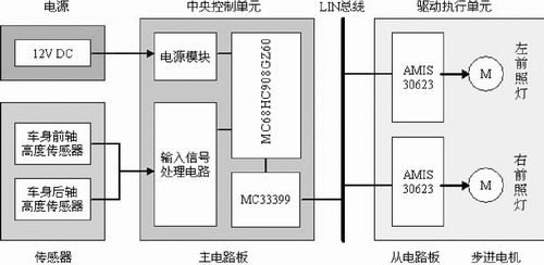
System Hardware Design Body Height Sensor The main principle of the system is to determine the tilt angle signal of the vehicle by measuring the distance difference between the two reference points (about the front and rear axle positions) in the vehicle to the ground, thereby making the level adjustment. The photoelectric coded vehicle height sensor can be selected to convert the change in the height of the vehicle body (change in the amount of suspension deformation) into the rotation of the sensor shaft, and convert the detected rotation angle signal into a voltage signal input to the MCU. In the experiment, the body height sensor is installed one inside each of the left front wheel and the left rear wheel.
The central control unit of the central control unit system uses the MC68HC908GZ60 chip produced by Freescale to be the main MCU, and the other necessary components constitute the control unit circuit. The main features of the chip are: 8-bit HC08 CPU, rich development resources, good compatibility; on-chip 60KB Flash EEPROM, 2KB RAM; 24-channel A/D conversion module, 10-bit precision.
In addition, the Freescale MC33399 chip is connected to the core MCU through the SCI port as a LIN bus transceiver. The chip can drive up to 16 nodes.
The reason why the LIN bus is chosen is that it is already a popular one in the car bus. Its advantage is that the chip is inexpensive and cost-effective. The LIN bus signal transmission rate can reach 19.2kbps, which is generally used in control situations where the safety requirements of automobiles are not high, such as electronically controlled doors and windows, and lamp switch control.
The schematic diagram of the main circuit of the LIN bus is shown in Figure 2. 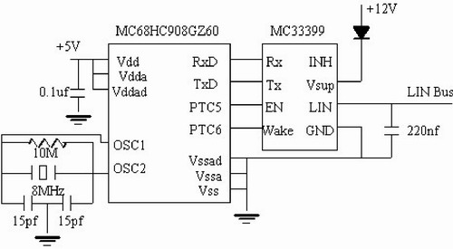
Figure 2 Schematic diagram of the main circuit of the LIN bus The drive execution unit drives the execution unit, mainly by acquiring the signal on the LIN bus to control the rotation of the stepping motor, thereby driving the headlight reflector to rotate in the vertical direction to complete the horizontal dimming.
Here I chose the AMIS-30623 stepper motor control chip from AMI Semiconductor. The chip is a highly integrated chip with built-in power modules, controllers, LIN bus transceivers and stepper motor drivers. Its main features are: maximum peak current output of 800mA; stepper motor drive with up to 16 subdivisions; built-in acceleration and deceleration algorithm; fully compatible with LIN1.3 specification.
Since the AMIS-30623 chip itself cannot be reprogrammed, all operations are performed by calling the internal functions of the LIN bus, so it is very easy to use. The built-in acceleration and deceleration algorithm is very effective for controlling the stepping motor variable speed motion.
The schematic diagram of the LIN bus slave node circuit is shown in Figure 3. 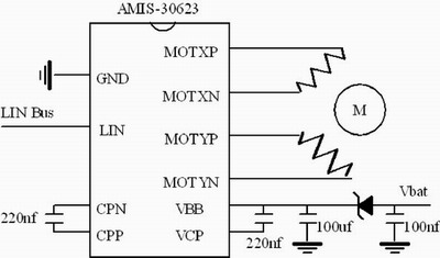
Figure 3 Schematic diagram of the LIN bus slave node circuit
This article refers to the address: http://
In terms of system software design software, 1ms timing interrupt acquisition is used, and each time an interrupt arrives, a set of sensor output voltage values ​​are taken. After pre-judgment, the valid data is retained and brought into the formula calculation to obtain the target position to which the stepper motor needs to be rotated. The signal is sent to the corresponding AMIS-30623 chip through the LIN bus, and the stepping motor is controlled to smoothly move to the corresponding position in the manner of acceleration-constant speed-deceleration. The program is compiled in the Freescale CodeWarrior 5.7.0 environment. The main program flow is shown in Figure 4. 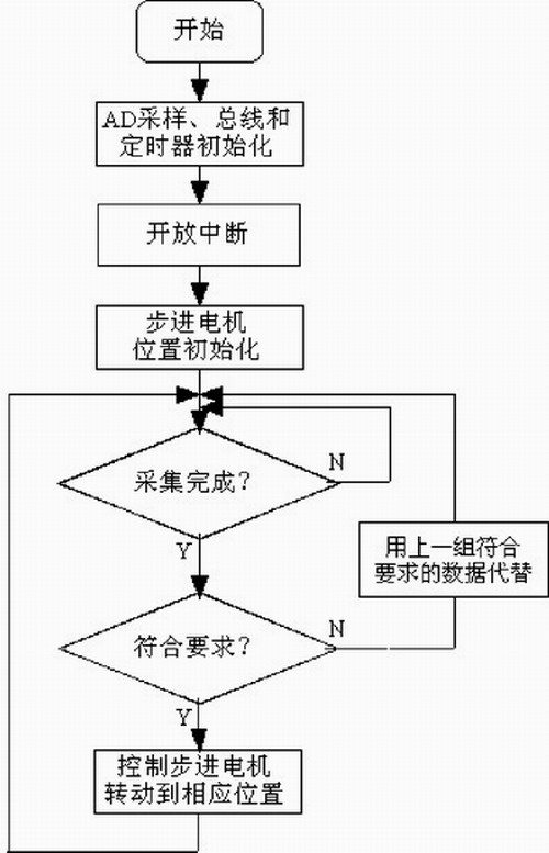
Figure 4 system main program flow chart
Experimental Results In order to verify the dynamic dimming performance of the system, an experimental platform capable of simulating the car's pitching motion was built in the laboratory environment. During the experiment, the control platform itself performs pitching motion according to a certain amplitude. The step response time of the dimming system is about 420ms, the adjustment time is less than 1s, and the steady-state error is about 0.035°, which satisfies the basic requirements of dynamic auto-dimming.
Conclusion The system implements the basic functions of automatic dimming of automotive headlamps, laying the foundation for further development of the more complex Adaptive Frontlighting System.
In addition, the system is actually a set of small power stepper motor control system based on LIN bus and single chip microcomputer. As a low-cost, fault-tolerant local bus, LIN bus is being used more and more widely in environments such as automotive and industrial control. The system is easy to develop, easy to maintain, and low in cost. It can be added to up to 16 sub-nodes. The software is fully compatible before and after the node is added and removed, and no reprogramming is required. Therefore, this design scheme has certain promotion value in the field of small power stepper motor control.
Micro LED light in cluster design, it is handmade by workers.The popular length is 1M,2M,3M ,5M.Light effect includes steady,chasing, RGB.The LED bulb is in white,warm white,red,blue,green,yellow,amber,multicolor,RGB.The design is very novelty.You can roll it in a circle and then turn to another design.The cluster design is more and more popular in the recent years.Daily & festival light for indoor & outdoor decoration. Operating by low voltage for safety and convenient use.
Cluster Lights
Cluster Lights,Cluster Led Lights,Led Traffic Light Lamp,Effect Laser Light
Heshan Jianhao Lighting Industrial Co., Ltd. , http://www.sunclubtw.com