introduction
This article is based on the open source operating system MeeGo developed by Nokia and Intel Corporation. The Linux input subsystem based on kernel object is used to design the touch screen driver. The solution greatly facilitates the development of touch screen drivers and can be applied to electronic products such as car entertainment, netbooks, and smart phones.
1 capacitive touch screen principle
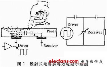
The capacitive touch screen is operated by the current sensing of the human body, and is divided into a surface capacitive type and a projected capacitive type. The former cannot recognize multiple points, and the latter can recognize multiple points, so the design uses a projected capacitive touch screen. The projected capacitive touch screen is a sensor that uses a touch screen electrode to emit an electrostatic field line, and is divided into an alternating capacitance and a self-capacitance. The design uses an interactive capacitive touch screen. It is made of ITO (Indium Tin Oxide) on the surface of the glass to make lateral and vertical electrodes. The intersection of the two sets of electrodes will form a capacitor, that is, the two sets of electrodes constitute the two poles of the capacitor.
When the capacitive screen is touched by a finger, the finger absorbs a small current, which changes the fit between the electrodes near the touch point, which changes the capacitance between the two electrodes. When detecting the size of the projected capacitive screen, the lateral electrodes sequentially transmit signals, and all the electrodes in the longitudinal direction receive signals at the same time, so that the capacitance value of the intersection of the two electrodes can be obtained, that is, the capacitance of the entire touch screen plane. The coordinates of each touch point can be calculated according to this, and FIG. 1 is an equivalent circuit diagram of the projected capacitive screen.
2 Linux input subsystem
The Linux Input Subsystem (hereafter referred to as the Input Subsystem) is implemented based on the kernel object kobject and is used in the Linux 2.6.35 kernel. With this mechanism, the kernel outputs various types of messages of the device to the user space through the input subsystem, which facilitates the management of the device. The input subsystem consists of three parts: the system core layer, the driver layer and the event processing layer. An input event such as mouse movement, keyboard key press, etc., reaches the user space through the driver layer, the system core layer, and the event processing layer, and is transmitted to the application.
In this way, when designing the driver, only the implementation of the driver layer needs to be considered, which reduces the workload and reduces the design difficulty. In addition, the subsystem-based design improves the portability and adaptability of the driver, because the subsystem-based driver design does not need to consider the interface of the upper layer reporting input device, this work is done by the input subsystem, and the input is done. The subsystem has versatility to the upper interface, which can extend the scope of the driver. Figure 2 is a block diagram of the Linux input subsystem.

3 touch screen driver design
3.1 How the touch screen driver works
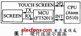
This design focuses on the overall design of the touch screen driver, which is also applicable to other touch screen driver design and development. This design can use the SPI bus as the interface between the touch screen and the processor. The hardware connection diagram is shown in Figure 3. TOUCH SCREEN is a capacitive touch screen. It can use FT5201 capacitive full-screen touch chip. INT is an interrupt pin. When the touch screen is touched, the interrupt processing program is triggered by the INT pin. The CPU can use Intel's Atom D510 processor.
The SPI bus is a high-speed, full-duplex, synchronous communication bus that operates in master-slave mode. There are four lines: SDI (data input), SDO (data output), CLK (clock), CS (chip select). ). In order to exchange data with peripherals, the SPI bus's output serial synchronous clock phase and polarity can be configured according to the peripheral operating requirements. The Clock Phase (CPHA) can be configured to select one of two different transmission protocols for data transmission. If CPHA=0, the data is sampled on the first edge of the serial synchronous clock (rising or falling); if CPHA=1, the data on the second edge of the serial synchronous clock (rising or falling) is sampling. The clock polarity (CPOL) has no significant effect on the transmission protocol. If CPOL=0, the idle state of the serial synchronous clock is low; if CPOL=1, the idle state of the serial synchronous clock is high.
We are offering Solar Led Street Light designed with precision to ensure optimum performance. Our offered light is manufactured with best quality components using latest techniques. Our offered light is rigorously checked at various quality parameters to ensure its flawlessness. Provided light is used to light the streets and is available in various specifications as per client`s requirement. We provide our light at an economical market rate.
50W Integrated Solar Street Lights
50W Integrated Solar Street Lights,Smart Solar Street Light,50W Solar Street Lights,50W Integrated Solar Street Lamp
Yangzhou Bright Solar Solutions Co., Ltd. , https://www.solarlights.pl