Over the past decade, automotive electronics has developed rapidly. Many functions that have been implemented with motors have been converted into electronic modules. The best example is the door device. Power windows, power mirrors and door locks controlled and driven by an electronic control unit (ECU) have become standard equipment in almost all new cars. Broadly speaking, electronic door systems have two different architectures. The first is a lumped system, usually it has a central module to control and drive every load in all doors. The second type is a distributed system, whose door functions are implemented in multiple ECUs.
Although the lumped architecture is still used in some models due to its low cost, it is being phased out because: 1) The central module method requires a large number of direct connection wiring, which increases the weight, wiring cost and cable short circuit Risk; 2) The function of a single module is limited, and it is impossible to embed all the required functions, such as comprehensive protection, diagnosis and communication interface; 3) Large-sized modules are also difficult to assemble. These shortcomings have led to the rapid development of electronic door system architecture in a distributed direction.
There are currently two standard automotive protocols for connecting distributed ECU modules, namely CAN and LIN. The main door functions can be implemented in different ways via the CAN / LIN interface. One of the most popular is the "door area module" or simply "door module" method. In this method, some major door function modules, such as door locks, rearview mirrors, window lifters and auxiliary lighting, are controlled and driven by separate ECUs.
The load characteristics and functions in the door modules vary widely. The challenge for system designers is to efficiently drive all loads while meeting design specifications and cost goals. As the world's leading supplier of automotive semiconductor components, Infineon Technologies provides a full range of products that can implement different drive strategies for different loads of door modules. This article will introduce the characteristics of these loads and the corresponding driving strategies.
System division and main load of door module
The door module is usually composed of three main functional modules: 1) microcontroller; 2) basic system functional modules including power supply, CAN / LAN communication and circuits that perform external event monitoring and signal detection; 3) phase with external load Connect the driver and power circuit. The typical system division of the door module is shown in Figure 1.
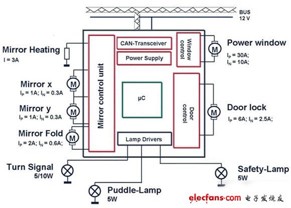
Figure 1: System partition and load characteristics.
The load types of the door modules include DC motors, lights, LEDs and heating coils. Figure 1 also shows some of their characteristics. In order to efficiently drive these different functions and types of loads, different driving strategies are required.
Large load drive strategy: relay or smart device?
For large loads such as window lift motors, there are usually two different driving methods: the first is a relay-based method, and the second is the use of semiconductor devices. The strategy of using relays is still widely used so far. The main reason is that the hardware cost is low, the technology is mature, and it can handle large currents well. However, this strategy also has many shortcomings:
1. The relay cannot provide any protection for itself and the whole machine;
2. The relay solution cannot achieve PWM control;
3. Usually the relay itself is relatively large and requires a fuse box;
4. As a moving part, the mechanical reliability of the relay is low;
5. The relay itself does not have any diagnostic function. It requires external devices such as shunt resistors and op amps to achieve current monitoring;
6. When more switching times are required (such as turn signal application), the electronic life of the relay is very limited;
7. The relay solution requires more external components to form a basic circuit, such as fuses, pre-drivers (generally a pair of Darlington tubes) and flywheel diodes;
8. The fuse and relay solution generate more heat, because the relay coil and contacts, as well as the fuse itself and the shunt resistance have large power losses.
The emergence of intelligent switches and bridges has opened the door to solving the above problems. Some new devices, such as Infineon's NovalithIC, can provide suitable solutions for high-current motor drive design. The BTS7960 is the first member of the NovalithIC fully integrated high-current half-bridge series product. It contains three independent chips in a TO-263 package: a p-channel MOSFET as its high-side substrate and an n-channel MOSFET as its low-side substrate, there is also a driver chip. These three chips are mounted in a common lead-frame using chip-on-chip and chip-by-chip technology.
The path RDS (ON) of the BTS7960 is 17 milliohms at 25 ° C. Its p-channel and n-channel MOSFETs are manufactured using different processes, thus ensuring fast switching of high-side and low-side switches and avoiding crossover Current. This design is different from most bridges that use charge pumps and have a limited maximum switching frequency, so it helps to implement high-frequency PWM control schemes and some new functions, such as "soft" opening / closing windows, and has good EMI performance.
The driver IC is directly connected to the microcontroller and can perform comprehensive protection and diagnostic functions. Protection features include current limiting, undervoltage / overvoltage lockout, overtemperature and complete short circuit protection. Diagnostic functions include fault status flags and current monitoring, the latter of which is often necessary when implementing anti-pinch-off strategies. Some special functions such as integrated dead time generation are also integrated to assist the DC motor drive.
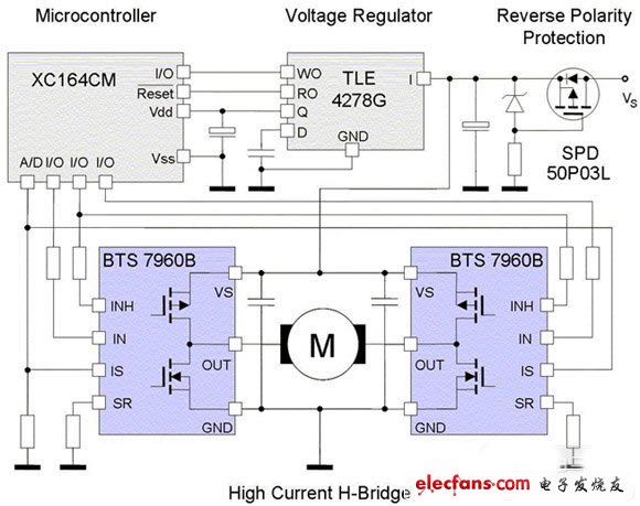
Figure 2: A typical application circuit of BTS7960.
The BTS7960 is therefore an excellent alternative to relay solutions in protected high-current motor drive applications in door modules. A typical application circuit for driving a large load such as a window lift motor with BTS7960 is shown in Figure 2.
Wireless Charging Power Banks,Fast Charging Wireless Power Bank,Power Banks,Wireless Power Banks
Dongguan Guancheng Precision Plastic Manufacturing Co., Ltd. , https://www.dpowerchargers.com