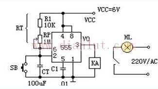
The circuit below is a photo exposure timer made with a 555 monostable circuit.
working principle:
When the power is turned on, the timer enters a steady state. At this time, the voltage of the timing capacitor CT is: VCT=VCC=6V. For the equivalent trigger of 555, both inputs are high level, that is, VS=0. The relay KA does not pull in, and the normally open point is open. The exposure light HL does not light up.
After pressing the button switch SB, the timing capacitor CT is immediately placed to zero voltage. Then the input of the equivalent trigger of the 555 circuit becomes: R=0, S=0, its output becomes high level: V0=1. The relay KA is sucked, the normally open contact is closed, and the exposure light is illuminated. When the button switch is pressed, it is released immediately, and the power supply voltage is charged to the capacitor CT through the RT, and the steady state starts. When the voltage on the capacitor CT rises to 2/3VCC and is 4 volts, the timing time has expired. The input of the 555 equivalent circuit flip-flop is: R=1, S=1, so the output is flipped to a low level: V0= 0. The relay KA is released and the exposure lamp HL is turned off. At the end of the transient steady state, there is a return to steady state.
Fixed Attenuator,Rf Fixed Attenuator,Microwave Attenuator,Fixed Coaxial Attenuator
Chengdu Zysen Technology Co., Ltd. , https://www.zysenmw.com