Mobile power is a popular personal device for portable electronic products such as smartphones or tablets, and its stylish and thin form factor means limited battery capacity. The mobile power source is a portable secondary battery for storing energy when AC power cannot be used.
Figure 1 shows a mobile power panel with two USB ports. One port is a mini USB that connects the power cord to a USB charging adapter to store energy in the mobile power source. Another USB port is a standard Type A USB port for charging a smartphone or tablet on the road.
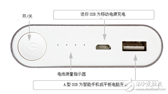
Figure 1: Mobile Power Panel
Depending on the form factor and budget, mobile power supplies can use different batteries. Figure 2a shows a mobile power supply for a smartphone with a battery capacity of several thousand milliamps (mAh) using a lithium polymer battery to achieve a thin profile. Another battery with a capacity of tens of thousands of mAh is usually a 18650 battery (a cylindrical battery with a diameter of 18 mm and a height of 65 mm) to achieve high charging capacity at a reasonable cost. Figure 2b is an example of such a mobile power source with a plurality of 18650 cylindrical battery packs connected in parallel within the housing.
The shape of the mobile power supply determines the size and capacity of the mobile power supply. There are many other technical issues to consider during the development of mobile power. Table 1 lists the basic application requirements and technical challenges for mobile power charging and discharging.
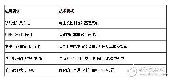
Table 1: Mobile Power Application Requirements and Technical Challenges
Figure 3 is a block diagram of a two-stage power supply; this is one of the most straightforward solutions. The first level is a single-cell battery charger, which can be a linear charger such as the bq24090 or a switching charger. The advantages of linear chargers are low cost, low EMI and small solution size. For high-capacity mobile power supplies ranging from a few thousand milliamp-hours to 10,000 mAh, a switching charger is needed to reduce charging time and temperature rise. The second stage is a boost converter, such as the TPS61088, which boosts the battery voltage to 5V for USB based on output current and cable resistance. The two sets of switches and inductors perform charging (red line) and boost (blue line), respectively.
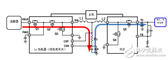
Figure 3: Two conversion stage mobile power supplies
The two-stage approach requires two sets of switches and inductors to perform buck charging and boost on-the-go (OTG), increasing the total cost of the solution. A single-chip fully integrated mobile power IC, like the bq24195 and the high-voltage fast-charging bq25895, requires only one set of switches and inductors to perform the charging and boosting functions. Figure 4a shows the mobile power charging mode (red thin line) and bypass mode (red thick line).
When the adapter mini USB cable is plugged into the mobile power source, the charger initiates a D + D-detection to determine the magnitude of the input current and sets the charger input current to not exceed the detected value. If the device is connected to the Type A USB terminal via a cable, the adapter current will ensure that the bypass handset is charged (the thick red line on Figure 4a) as a high priority due to the charger's input current dynamic power management function - the remaining extra power Charge the battery.
The blue line on Figure 4b is the mobile power supply operating in OTG boost mode. The adapter has been unplugged and the battery voltage has risen to about 5V to charge the phone. The switch and inductor bank for operation in buck charging mode now charges the handset in boost-discharge mode operation; no additional components are required, reducing cost.
In order to charge and discharge the battery not only during the charging mode of all three chargers, but also during the discharge boost mode of bq24295 and bq25895, the battery temperature is sensed with a negative temperature coefficient (NTC) resistor to ensure the desired battery operating.
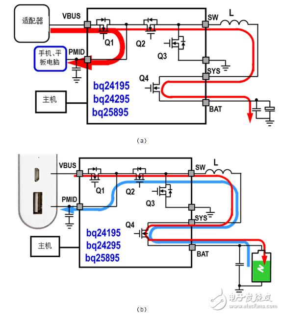
Figure 4: Mobile Power Bypass and Charge Mode (a) and OTG Boost Mode (b)
As you can see, the single-chip fully integrated power IC product line mentioned in this blog has only one set of switches and inductors. The bq25895 integrated ADC can be used with the host for battery capacity measurement. The solution simplifies design, reduces BOM cost, and addresses many of the challenges of designing mobile power, including high integration of mobility, input current limited D + D-detection, and charging to achieve the desired operating temperature range Battery temperature detection in discharge mode. Check out TI Designs below to get started with your mobile power design.
Door Lock Motor Characteristics 1. No direction: don't need to distinguish the door direction, left and right sides, both inside and outside the door, can be universal. (convenient purchase locks and reduce inventory).


2. Power: the power consumption is only equivalent to one 5 of the electric control lock, electric lock, 3 A magnetic lock power to open the door, often consumes 0.27 A. And spiritual lock unlock instantaneous current is less than 0.5 A, reduced the entrance guard, talkback host power consumption.
3. No collision: close the door without collision, reduces the choice of door closers requirements (not necessarily with 65 kg of door closers, door closers are free to choose to suit the door), to solve the building door because the door closers clash of the hydrodynamic force is too high, it is not easy to make the door more deformation, prolong the service life of the body.
4. The voice is light: close the door automatically locked, no noise, solves the noise due to electric control lock itself.
5. Life is long, life is up to 350000 times
Operating temperature range:
Mini Door Lock Motor should be used at a temperature of -10~60℃.
The figures stated in the catalog specifications are based on use at ordinary room temperature catalog specifications re based on use at ordinary room temperature (approximately20~25℃.
If a lock motor is used outside the prescribed temperature range,the grease on the gearhead area will become unable to function normally and the motor will become unable to start.Depending on the temperature conditions ,it may be possible to deal with them by changing the grease of the motor's parts.Please feel free to consult with us about this.
Storage temperature range:
lock motor should be stored ta a temperature of -15~65℃.
In case of storage outside this range,the grease on the gearhead area will become unable to function normally and the motor will become unable to start.
Service life:
The longevity of Door Lock Motor is greatly affected by the load conditions , the mode of operation,the environment of use ,etc.Therefore,it is necessary to check the conditions under which the product will actually be used .The following conditions will have a negative effect on longevity.Please consult with us should any of them apply.
â—Use with a load that exceeds the rated torque
â—Frequent starting
â—Momentary reversals of turning direction
â—Impact loads
â—Long-term continuous operation
â—Forced turning using the output shaft
â—Use in which the permitted overhang load or the permitted thrust load is exceeded
â—A pulse drive ,e.g.,a short break,counter electromotive force,PWM control
â—Use of a voltage that is nonstandard as regards the rated voltage
â—Use outside the prescribed temperature or relative-humidity range,or in a special environment.
â—Please consult with us about these or any other conditions of use that may apply,so that we can be sure that you select the most appropriate model.
when it come to volume production,we're a major player as well .each month,we rurn out 600000 units,all of which are compliant with the rohs directive.Have any questions or special needed, please contact us, we have the engineer group and best sales department to service to you
Looking forward to your inquiry. Welcome to our factory.

Door Lock Motor,Mini Door Lock Motor,Door Lock Dc Motor,Door Lock Gear Motor
Shenzhen Shunchang Motor Co., LTD. , https://www.scgearmotor.com