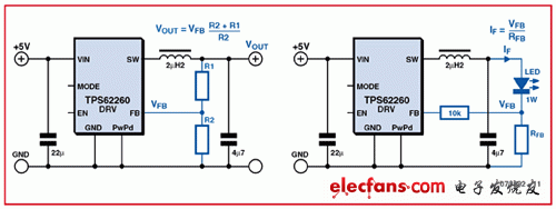
High-brightness LEDs are increasingly used in lighting applications. Here we will introduce a simple "ambient lighting", which uses only a small number of components. All three LEDs are powered by a constant current using a switching regulator, and the brightness control is done by an MSP430 microcontroller that can generate three PWM signals. The printed circuit board can be mounted in the table lamp with a frosted glass housing, or it can also be used with LED spotlights for indirect lighting. No matter how much power it consumes, current LEDs are usually driven by a constant current source. This is because the light output in lumens (lm) is proportional to the current. Therefore, all LED manufacturers stipulate parameters such as light output (sometimes called optical efficiency), viewing angle, and wavelength as a function of forward current IF, rather than as forward voltage VF as one would expect function. Therefore, we used an appropriate constant current regulator in the circuit. Constant current for high-brightness LEDs Most switching regulators on the market are configured as constant voltage sources instead of constant current sources. The conversion of the constant voltage regulator to constant current operation requires simple and slightly modified circuits. We used a current sense resistor whose voltage drop is adjusted instead of the voltage divider that is usually used to set the output voltage. Figure 1 shows a simplified diagram of the circuit.

Figure 1 A switching regulator can be configured as a voltage source or a current source LED brightness adjustment
There are two main methods for adjusting LED brightness. The first and simplest method is to use analog control to directly control the current flowing through the LED: reduce the brightness by reducing the current flowing through the LED. Unfortunately, this method has two serious drawbacks. First, the brightness of the LED is not strictly proportional to the current. Second, when the change in current exceeds the rated value of the LED, the wavelength of light emitted (and the resulting color change) may change with the change in current. These two phenomena are usually undesirable. A slightly more complicated control method is to use a constant current source that can provide the rated operating current of the LED. In this way, the additional circuit can use a given pulse-to-space ratio (mark-space raTIo) to quickly turn the LED on and off, thereby emitting less light on average, and it feels like the light intensity is reduced. Through the pulse interval ratio, we can more easily adjust the perceived brightness of the LED. This method is called pulse width modulation (or PWM).
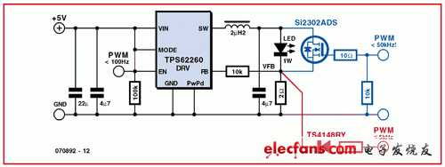
Using PWM for dimming as an example, we will see some methods for implementing PWM control using TPS62260. TPS62260 is a synchronous buck converter with integrated switching elements and a typical clock frequency of 2.25MHz. In the circuit in Figure 2, we show the possibility of connecting the PWM signal directly to the EN (enable) pin in black. The entire switching regulator circuit is turned on and off together with the PWM signal. Experiments in our experiments show that in this configuration, we can use a PWM frequency of up to 100 Hz. The advantage of this arrangement is its simplicity: no additional components are required. In addition, it is the most efficient method of implementation because the switching regulator generates very little quiescent current when it is turned off. The disadvantage is that the LED's response to the high level on the enable pin is delayed. This is because the switching regulator has a "soft start" function: when the device is turned on, the output current gradually increases until it reaches the rated LED current. In some applications, this rising slope may have some problems, because the wavelength of the LED light changes as the current gradually increases from its minimum value to the normal operating level. For example, in a LED backlight of a DLP projector or LCD TV panel, this change may not be acceptable to us. However, as far as this demonstration project is concerned, this effect cannot be seen with the naked eye. In the second variable (shown in red in Figure 2), the PWM signal is coupled to the error amplifier input of the TPS62260 through a small signal diode. In this circuit, a positive voltage of more than 600mV applied to the control input will overdrive the error amplifier input and thereby turn off the LED. Since this circuit does not use an enable input, it does not have a start-up delay associated with the soft-start function of the regulator, and the LED is turned on and off very quickly. Therefore, the change in output wavelength caused by the above-mentioned current ramp is negligible in this structure. In addition, we found in the laboratory that the PWM frequency can rise to 5kHz. The blue part in Figure 2 shows the third possibility. The PWM signal here is used to control the MOSFET connected to the LED. The MOSFET short-circuits the LED and allows it to be turned on and off more quickly. The regulator operates in constant current mode, and the current will flow through the LED or MOSFET. Some disadvantages of this method include the additional cost and low efficiency of the MOSFET: up to 180mW of power is continuously dissipated in the 2Ω current sense resistor. The advantage is the higher switching frequency: In some experiments, we have seen that the TPS62260 can successfully run at a state of 50kHz PWM frequency.

Figure 2 Three methods for implementing the dimming function

Figure 3 Using the JTAG connection (JP1), eZ430 connector (JP2) and rotary encoder (R1) based on the control part of the MSP430 microcontroller of this circuit

Figure 4 The actual circuit part of the circuit composed of three switching regulators configured as a constant current source and a 3.3V stable power supply built with discrete components
The core of this circuit (see Figures 3 and 4) is an MSP430F2131 microcontroller. Program it so that it functions as a triple PWM generator and read the value from the rotary encoder (R1). The encoder value is used to index a lookup table that contains the ratio of all red, green and blue LED pulse intervals. Then, the corresponding PWM signal will appear on the output pins TA0, TA1 and TA2 when the frequency is close to 122Hz. The intensity of this signal is sufficient to ensure that the LED does not flicker, because the eye smoothes a single light pulse into an average perceptible intensity value. In terms of actual implementation, we chose the PWM control method shown in red in Figure 2, which gives a good balance between circuit complexity and performance. Each LED, red (D14), green (D24) and blue (D34) is powered by a constant current from a single TPS62260 DC / DC converter. The 2Ω resistor sets the rated current flowing through the LED to 300mA. Using TPS62260's "big brother" grade product TPS62290 can get stronger current (up to 1A), which is packaged in the same way. Use small signal diodes (D13, D23, and D33) to couple the PWM signal. When the PWM signal is high, it will exceed the normal error signal input of the corresponding switching regulator, which has a limit voltage level of 600 mV. This means that the high level of the PWM signal will force the LED to turn off. When the PWM signal finally decreases, the regulator starts again and the LED lights up. The entire circuit is powered by a regulated 5V 1 A DC power adapter. A simple voltage regulator built with a resistor and a Zener diode reduces the 5V level to 3.3V for use with the MSP430 microcontroller. The circuit can be built on a printed circuit board as shown in Figure 5. There are three versions of the circuit board, and the difference between them is only in the footprint and arrangement of the LED connections. This allows the use of different types of LEDs, some of which are listed in the parts list.
Filter bandpass/lowpass/highpass
Bandpass Filter,Rf Bandpass Filters,Coaxial Bandpass Filter,Lowpass Highpass Bandpass
Chengdu Zysen Technology Co., Ltd. , https://www.zysenmw.com