introduction
Smartphones, mobile phones and other portable devices require smaller and smaller form factors and power consumption. At the same time, the complexity and functionality of the equipment continue to increase. This shows that the space occupied by each functional circuit is decreasing at an alarming rate. This application note describes a simple, space-saving method for solving two major problems with portable products. First introduce its high-precision, ultra-low-power battery remaining capacity estimation function; then introduce its compact low-power Li + battery overcurrent protection function.
Li + battery current monitoring
Accurate measurement of the current loss of the load can estimate the remaining capacity of the Li + battery. Connecting a small current-sense resistor between the Li + battery and the load can produce a voltage drop proportional to the load current in the resistance. The current-sense amplifier is used to detect the voltage drop across the resistor (typically tens of mV), and amplifies the signal according to the dynamic range of the analog-to-digital converter (ADC) to obtain an appropriate output voltage. This converter is usually integrated in the RF chipset or power management integrated circuit (PMIC), and the current-sense amplifier should be configured in the same phase as possible. This application has two main circuit requirements: small size and low power consumption, which is also a very attractive feature of portable devices.
Figure 1 shows the MAX9938 current-sense amplifier. At room temperature (25 ° C), the device has an ultra-low quiescent current of less than 1µA (maximum). It uses a miniature 1mm x 1mm, 4 solder ball UCSP (ultra wafer level package). Wafer-level packaging is an IC packaging process that uses solder balls instead of pins to obtain the smallest package size¹. The low input offset voltage of the current-sense amplifier can ensure the minimum voltage drop of the current-sense resistor, thereby minimizing the power consumption of the current-sense resistor itself.
In a typical portable device such as a smartphone, the peak current in transmit mode may reach 1A. Assuming the full-scale voltage of the ADC is 2.5V, for the MAX9938F with a fixed gain of 50, a 50mΩ current-sense resistor can be used. Therefore, the maximum voltage drop across the sense resistor is 50mV, and the maximum power consumption is 50mW. With an amplifier with a maximum input offset voltage of less than 500µV, the resulting error will be limited to less than 1% of the peak current.
If the system requires higher detection accuracy, you can use a 100mΩ current-sense resistor and a fixed gain of 25 MAX9938T. The offset error can be reduced to 0.5% of the peak current, but the power consumption of the sense resistor is doubled.
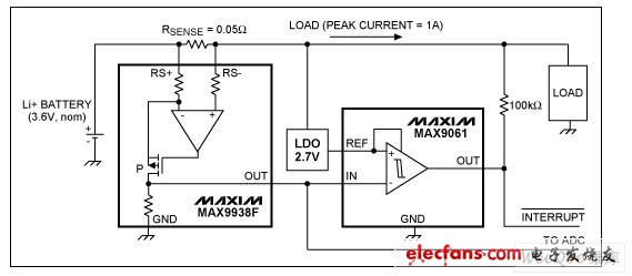
Figure 1. The MAX9938F current-sense amplifier is used to measure battery current, and the MAX9061 comparator is used to detect overcurrent events.
Overcurrent protection
If faulty components are used in the circuit, or in some cases too many software operations are initiated at the same time, overcurrent may occur. Whatever the reason, this failure condition must be notified to the central processor in the form of an interrupt.
In portable applications, it is best to use the MAX9061 comparator to achieve overcurrent protection (Figure 1). The MAX9061 uses an innovative design to supply its internal circuits with a reference voltage applied to the non-inverting input. This voltage can range from 0.9V to 5.5V. The inverting input can be as low as -0.3V and as high as 5.5V, regardless of the reference voltage. An open-drain output is used, so an external pull-up resistor is required. In most cases, the internal pull-up resistor of the microcontroller can be used. The unique and innovative architecture allows the comparator to be integrated in an ultra-small 1mm x 1mm, 4-ball UCSP package.
In Figure 1, the input of the MAX9061 is connected to the output of the current-sense amplifier. The maximum voltage is 2.5V, which corresponds to the peak battery current. The reference voltage can be connected to a low dropout (LDO) linear regulator with a voltage higher than the peak input, for example 2.7V. When the MAX9061 input is higher than the reference voltage, the comparator output is set to a low level and an interrupt is generated.
In addition to the advantages of a small package with a size equivalent to two 0402 resistors, the MAX9061 also has ultra-low power consumption and consumes only 100nA (maximum) bias current. To reduce the current, you can use the largest possible pull-up resistor, because the interruption is generated on the falling edge of the comparator, and the fall time is independent of the resistance of the pull-up resistor. If you need an output with the opposite polarity, you can choose MAX9060. When the reference voltage is higher than the input voltage, the comparator outputs a low level.
Circuit testing
Test the circuit in Figure 1 and replace the battery with a voltage source. Assume that the maximum voltage when the Li + battery is fully charged is 4.2V. This power supply provides 1A of current to the load through the current-sense resistor. The voltage source can be gradually reduced to 2.8V according to the law of battery discharge. Table 1 shows the test results. Figure 2 shows the gain curve of the MAX9938F. Using two test points, the gain error of the actual device test is 0.21%.
Table 1. MAX9938F input (VSENSE) and output (VOUT) measurements
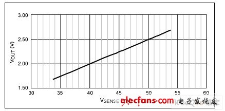
Figure 2. The gain curve of MAX9938F
Then set the voltage source above 4.5V to simulate over-current conditions greater than 1A. Figure 3 shows the response characteristics of the MAX9061, which generates an interrupt.
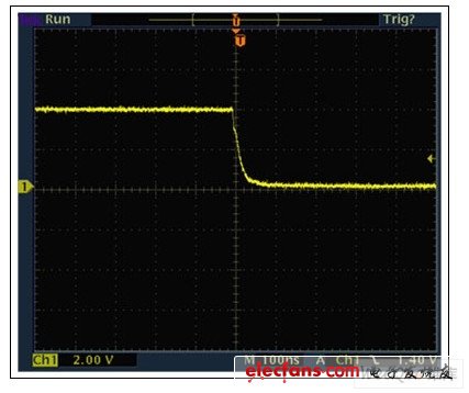
Figure 3. The MAX9061 generates an interrupt signal from high to low under overcurrent conditions
in conclusion
At present, as the size of portable products is getting smaller, the demand for high-precision, compact ICs is also increasing. This application note describes how to use the tiny, 4-ball UCSP package current-sense amplifier and comparator to implement simple battery management functions, such as: battery remaining capacity estimation and overcurrent protection.
About Cartoon Luggage Tags:
Lots of different animals live with us ,some of them are very cute ,like dogs ,cats ,monkeys ,many people love to live with them ,they are not only pets but family members ,so they really want to bring them when go for a trip ,but sometimes they are not convenient for travelling ,people will miss them so much ,so why not make a cartoon luggage tag with their figures ? You can see them everywhere,it seems like they go with you!
Cartoon Luggage Tags description:
1.Product name:Cartoon Luggage Tags,Animal Luggage Tags,Personalized Luggage Tags, Custom Luggage Tags , Cute Luggage Tags , Luggage Name Tags
2.Place of origin:Guangdong China
3.Color:any pantone color is available
4.Logo:silk printing,water transfer printing ,heat transfer printing .
5.MOQ:500pcs.
6.Package:1 pcs/opp,customized design is available.
7.Design:Customized
8.Certification:FDA,LFGB,SGS,ROHS,etc.
9.Usage:Gifts/recognizing luggage
10.Cartoon Luggage Tags photos for reference

Cartoon Luggage Tags,Animal Luggage Tags,Personalized Luggage Tags,Custom Luggage Tags,Cute Luggage Tags,Luggage Name Tags
OK Silicone Gift Co., Ltd. , https://www.oemsiliconegift.com