Challenges in driver assistance system development Automotive assisted driving (DA) system engineers typically use PC models to create complex processing algorithms for highly reliable adaptive cruise control, lane departure warning, and pedestrian detection. Developers value the PC algorithm model because it allows them to try and quickly evaluate different processing algorithms. However, in the final analysis, a well-designed electronic hardware solution is needed to achieve cost-effective mass production and deployment.
This article refers to the address: http://
Verifying the performance consistency of the algorithm between the deployable target hardware and the software algorithm model is a problem for many developers. Moving from floating point to fixed point calculations (such as the different methods used by trigonometric functions) can sometimes lead to significant differences between the reference software algorithm and the hardware implementation model. In addition, the input pattern stimulus has great uncertainty, which makes the verification algorithm performance consistency work more complicated.
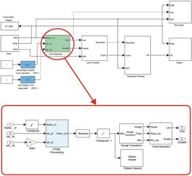
Figure 1 LDW top block diagram
For DA systems that typically rely on remote sensing devices (cameras, radar, etc.) input, the input information is the various road conditions and environmental conditions that the driver may encounter in actual driving. Engineers will find it challenging to design a processing algorithm that fully satisfies all situations and to verify the consistency of algorithm performance between the software model and the electronic hardware implementation.
One of Xilinx's tools, System Generator for DSP, provides an efficient and intuitive way for algorithm developers and system architects to move from Simulink PC models to real-time FPGA hardware implementations. This design tool with a high level of abstraction plays a key role in the design project jointly developed by Xilinx and eVS engineers. The goal of the project is to use System Generator for DSP to introduce a graphics processing algorithm for the car lane departure warning system using Xilinx FPGAs to improve overall performance, reduce costs, and reduce development time.
Lane Departure Warning Model The lane departure warning (LDW) system's overall function is to alert the driver when the vehicle inadvertently deviates from the lane being driven. A camera is placed in front of the vehicle in which the system is installed, and a road condition graphic can be captured to identify the lane boundary sign. The lane departure warning system continuously tracks the lane markings and the position of the vehicle relative to the lane markings. If the vehicle crosses the lane markings, the system will issue a warning.
MATLAB and Simulink are commonly used in the automotive industry and academia as algorithms and system-level design tools. In particular, Simulink has a high level of abstraction and provides graphical input, thus enabling automotive algorithm engineers to quickly and easily develop complex DSP algorithms.
Figure 1 shows the top-level block diagram of the LDW system model, which was designed using Simulink. The green block labeled Lane Detection includes a graphics pre-processing subsystem, and the processing steps for that subsystem are given in Figure 2. The lane detection function is designed to extract the road conditions that are most likely to represent the lane markings.
In order to improve the performance of edge device noise detection, the first step of the process is 2-D 5×5 Gaussian Noise Suppression (GNR); the second step is Histogram Widening (HST), which developers can use to enhance the graphics contrast. Use the entire grayscale range as much as possible; the third step is the horizontal/vertical gradient (HVG), which enhances the pixel with a large change in local intensity. Developers can perform HVG by calculating the 2-D 5×5 gradient of the graph.
System Generator Tools Overview
The System Generator for DSP design tool runs in Simulink. It uses Xilinx's DSP module set for Simulink and will automatically call the Xilinx CORE Generator tool to generate a highly optimized DSP building block netlist that can access the Xilinx DSP blockset through the Simulink library browser. The library browser can be launched from the standard MATLAB toolbar. There are more than 90 DSP building blocks available for building DSP systems, including FIR filters, FETs, FEC cores, embedded processing cores, memory, arithmetic blocks, logic blocks, and bit-wise blocks. Each block implements cycle precision and bit precision, which can be configured one by one for delay, area and speed performance optimization, I/O port count, quantization, and rounding.
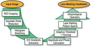
Figure 2 LDW pre-processing function chain
Below, it is worthwhile to explore how to build a graphics processing algorithm model in System Generator for DSP. For the sake of simplicity, choose GNR as an example, which is the first module of the graphics preprocessing process.
Random variations in the implementation of GNR functional strength values ​​(ie, noise) by System Generator often compromise image quality. This change appears as a Gaussian or normal distribution and is more common in different sensors (ie CMOS cameras). A linear smoothing filter is the best way to eliminate Gaussian noise, and in many cases it eliminates other types of noise. To achieve this, a linear finite impulse response (FIR) filter can be implemented by using pixel weighted sums in successive windows.
Before we started implementing the GNR System Generator module, we implemented its behavioral model in MATLAB. This can be done with just two lines of code. First, the kernel needs to be calculated, specifically describing the mask size (this example is set to 5 × 5) and the Gaussian threshold. The input image can then be filtered by convolution.
N_mask = fspecial('gaussian', 5, 0.8);
Out_img = conv2(in_img, n_mask, 'same');
In addition, this behavioral model can be used and the filter coefficients can be tested with actual video data to adjust the mask coefficients. You can also verify that the output of the System Generator for DSP subsystem is equal to the output of the MATLAB function (within the specified error range, because MATLAB works in floating point mode and System Generator works in fixed point arithmetic). Verify the hardware.
The 2-D GNR module processes the input image in a streamlined (ie, progressive) manner. Figure 3 shows the top-level block diagram of the System Generator top-level block diagram and Gaussian noise suppression for the entire pre-processing chain.
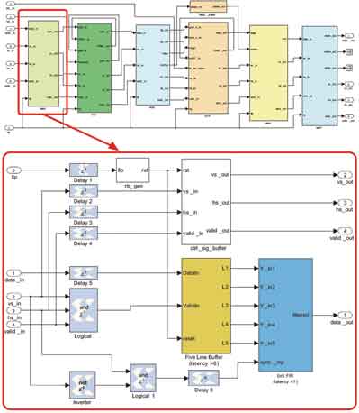
Figure 3 Block diagram of top-level preprocessing and Gaussian noise suppression
System Generator FPGA synthesis results developers must design at a cost level that is suitable for mass production when developing a driver assistance system.
The die resources required to achieve a certain processing performance will determine the size of the FPGA device they need, which in turn determines its cost.
The XA Spartan-3A DSP 3400 is targeted during the implementation of the lane departure warning preprocessor. Use this approach and use the model to support development activities in future planning. However, an analysis of the resources occupied by the preprocessing function indicates that the design is suitable for much smaller devices.
Table 1 shows the resource occupancy of the GNR block on the XA Spartan-3A DSP 3400 device. In the calculation, it is assumed that the frame rate of the grayscale input image at the VGA resolution is 30 Hz (that is, the input data rate is 9.2 MS/s).
From a timing performance perspective, the GNR design operates at a clock rate of 168.32 MHz and accepts input data at data rates up to 18.72 MS/s.
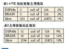
The total resources required for the entire lane detection preprocessing subsystem are shown in Table 2.
Corresponding timing performance analysis shows that the clock frequency is 128.24MHz and the highest input data transmission rate is 14.2MS/s.
Based on the above analysis of required resources, the pre-processing function is even available for the XA Spartan-3E 500, which is approximately 1/7 the density of the XA Spartan-3A 3400A device.
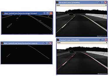
Figure 4 LDW processing model output
Results Figure 4 shows the performance of an LDW system, including FPGA-based image preprocessing for laneline reserve extraction. You can see the input frames in the two images on the right. The pair of images on the left shows the performance of the pre-processing functions we implemented in the FPGA. The picture in the upper left corner shows the amplitude of the edge detection function after thresholding. The bottom left image was taken after edge refinement and lane line mode search processing. Clearly, the LDW preprocessor is very efficient at taking road maps and reducing data to basic lane line selections. The yellow and red lines in the upper right and lower right images respectively represent the instantaneous tracking calculation results for the lane markings based on the simple straight road model.
LiFePO4 For UPS/Back-Up/Telecom
Deep Cycle Battery,LiFePO4 Battery 200ah,12V Lithium Battery
LiFePO4 for Transportation Co.,Ltd , http://www.nswindenergy.com