introduction
The stereoscopic rotating LED, also called POV LED, is an electronic product that uses the persistence effect of the human eye to display information such as graphics and animation. It is a rotating bracket, and the LEDs arranged on the bracket are controlled by the single chip at a specific position. Lights up or off, thus displaying a specific character or figure. In the wireless power supply technology, when a high-speed motor is used to drive the LED to rotate, a state of a columnar LED display screen is visually produced. The displayed characters or graphics appear to be floating in the air, not only beautiful, but also novel, suitable for many occasions. In this paper, the peripheral circuit is built with the single-chip microcomputer as the main control component. The two 74HC595 chips are used to control 16 LEDs. According to the Hall principle, an AH1344 Hall element is used to detect the magnetic induction change to display specific characters.
1 STC11F02E microcontroller introduction
STC11F02E is one of the STC11/10xx series MCUs designed and produced by Hongjing Technology. Its characteristics are: high speed, 1 clock/machine cycle, enhanced 8051 core, 8~12 times faster than ordinary 8051; wide voltage, 5.5~4.1 V/3.7V; low power design; operating frequency, 0 ~ 35MHz, with 2kB of on-chip Flash program memory, 2kB of EEPROM memory and 256kB of on-chip SRAM data memory, small size and low price.
2 hardware design
The 16 I/O ports of the STC11F02E control two 74HC595 chips, and then the eight I/O ports of the two 74HC595 control 16 LEDs to be off. The program is written in the MCU. When the motor is powered, the MCU is located. The board will rotate with it. According to the Hall sensor principle, whenever the Hall element is turned to the vicinity of the magnetic steel, the output of the circuit becomes a low level, thereby generating a falling edge, so that the interrupt port of the MCU receives a falling edge and issues an interrupt, so that the circuit can be synchronized, and finally Show specific characters. The rotating device is composed of a Hall sensor module, an LED display module and a power module.
Hall sensor module: Hall sensor is a magnetic sensor, this design uses AH3144 chip. AH3144 is a unipolar Hall switching circuit. It is a magnetic sensitive circuit composed of a voltage regulator, a Hall voltage generator, a differential amplifier, a Schmitt trigger and an open collector output stage. The input is magnetic induction and output. Is a digital voltage signal. It is a magnetically sensitive circuit that operates on a single pole and is suitable for operation under rectangular or cylindrical magnets.
LED display module: 16 side-by-side LEDs are used to display text and patterns by the "visual persistence effect" of the human eye. The rotary LED display is a new type of display that realizes graphic display by synchronously controlling the LED position and lighting state. The structure is novel, the cost is low, and the viewing angle is 360°.
Power module: 220V AC voltage through the transformer output is 12V AC voltage, and then through the bridge rectification into a unidirectional pulse voltage, and then through the filter circuit to become a relatively stable DC voltage, and finally through the 7805 to stabilize the output of 8V DC.
Wireless power supply module: Wireless power supply is a new technology that is convenient and safe. It does not require any physical connection, and the power can be transmitted to the load at a close distance without contact. This design uses NE555 multi-resonant circuit to achieve wireless power supply. The hardware schematic diagram of the stereo rotating LED circuit is shown in Figure 1.
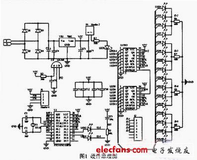
Figure 1 hardware schematic
3 software design
The main program software is mainly a program of the LED display module. The main program first initializes the system environment, sets the port P1.1, P1.2 strong pull-up, then starts the delay, initializes the 74HC5 95 shift register, allows the external interrupt INT0 interrupt, sets the falling edge trigger interrupt, turns on the total interrupt, Lights up LED1 and LED2 and enters the loop waiting for interrupt. The 74HC595 shift register receives the current timer value, latches it and then transfers the characters in the font to the output. The final 16 LEDs can display the characters normally.
The LED display is based on the principle of 16&TImes;16 dot matrix display. When 16 LEDs are rotated 16 lines, a word will be displayed. Since the bus of STC11F02E is 8 bits, it needs to be split into two parts when displaying one word. It is generally divided into upper and lower parts. The upper part is composed of 8&TImes; 16 dot matrix, and the lower part is also composed of 8&TImes; 16 dot matrix. For example, the word "Shen" is shown in Figure 2.
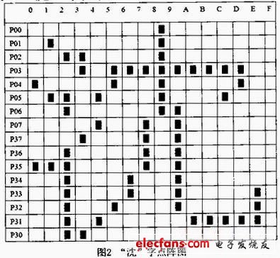
Figure 2 "Sink" dot map
In this example, the MCU first displays the upper half of the first column in the upper left corner, that is, the P00-P07 port in the 0th column. The direction is P00-P07. When the Chinese character "Shen" is displayed, P04 lights up and is arranged from top to bottom. P00 is off, P01 is off, P02 is off, P03 is off, P04 is on, P05 is off, P06 is off, P07 is off. That is, the binary is 00001000, and the conversion hexadecimal is 08h.
After the first column of the upper half is completed, continue to scan the first column of the lower half, still scanning from top to bottom, that is, scanning from P37 to P30, and P35 is lit, the binary is 00100000, and the hexadecimal is 10h.
Then the MCU turns to the second column of the upper half, P01 and P05 are lit, which is 01000100, that is, hexadecimal 44h. After this column is completed, the lower half is scanned, and P35 is lit as binary 00100000, which is hexadecimal 20h. . According to this method, the following scan is continued, and a total of 32 8-bit scans can be used to obtain the scan code of the Chinese character "sink".
According to the internal machine cycle of the microcontroller is 1/12, the crystal oscillator is 12MHz, and the frequency of executing one instruction can be calculated by the formula (1) to be 1MHz, and the period is 1μs.
1/12&TImes;12MHz=1MHz (1)
When the LED rotates, it is equivalent to transmitting every two characters, setting the delay to 600μs. Since the visual persistence time is 0.1~0.4s, when the LED rotates one week, people see that the last LED is still bright. So, I feel that the word "Shen" is always displayed.
Since the board radius of this design is 11.5cm and the LED radius is 0.5cm, this display can display up to 9 characters.
4 Conclusion
The three-dimensional rotating LED of this design adopts the wireless power supply mode, and the rotation is very quiet and stable, the speed of the motor is very fast, and the rotation is not so fast. Since this design uses a single row of 16 LEDs, the other end of the board must have a heavy object to maintain balance. The two coils in the wireless power supply circuit must not be too far apart and must be kept within 3 cm, otherwise a sufficiently stable voltage cannot be provided.
Fume Vape
Shenzhen Uscool Technology Co., Ltd , https://www.uscoolvape.com