introduction
With the continuous development of computer network technology, special integrated chip technology and field bus technology, the requirements for the measurement accuracy of industrial electricity meters and the real-time nature of power data transmission are constantly increasing. At present, the watt-hour meters equipped on electric locomotives in China are basically traditional mechanical watt-hour meters. Although mechanical watt-hour meters have the advantages of good anti-interference and anti-vibration, but their accuracy is poor, and the electric power data requires human reading Disadvantages such as real-time transmission. ADE7755 is an enhanced version of AD7755, which solves the problem that the output of F1, F2 and CF of AD7755 is not synchronized and there is no output at low power. That is to say, AD7755 has no output from F1 and F2 and CF has output when the load is 8-13mA, and there is no output from both under the load of less than 8mA, resulting in a large measurement error. There is basically no difference between the two in other respects. First, the AD7755 has been discontinued. The data manual of the ADE7755 is basically the same as the previous AD7755, with slight changes. ADE7755 is a high-accuracy energy measurement integrated circuit whose technical indicators exceed the accuracy requirements specified in IEC1036. The ADE7755 only uses analog circuits in the analog-to-digital converter (ADC) and the reference source. All other signal processing (such as multiplication and filtering) uses digital circuits, which allows the ADE7755 to maintain high accuracy in harsh environments. And long-term stability. ADE7755 pins F1 and F2 output the average value of active power in the form of lower frequency, which can directly drive the electromechanical meter or MCU interface. Pin CF outputs the instantaneous value of active power in the form of higher frequency, which is used for verification or interface with MCU. ADE7755 contains a monitoring circuit for AVdd power pin. Before Avdd rises to 4V, the ADE7755 remains in the reset state. When AVdd drops below 4V, the ADE7755 is also reset, at this time F1, F2 and CF are not output.
Hardware circuit design
At present, the widely used mechanical, electromagnetic and electromechanical watt-hour meters generally have a defect that they cannot transmit power data in real time, and each has weaknesses such as poor accuracy or poor anti-interference ability. The author combines the currently popular fieldbus technology and AD company's ADE7755 power measurement chip and Philips P87C591 single-chip microcomputer. The internal phase matching circuit makes the phase of the voltage and current channels always match (phase error in the range of 45-65Hz) No more than ± 0.1 degrees), regardless of whether the high-pass filter (HPL) in channel 1 is on or off. The internal no-load threshold characteristics ensure that the ADE7755 does not creep when it is no-load.
The overall circuit block diagram is shown in Figure 1:
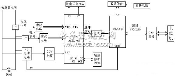
Figure 1 overall circuit block diagram
In Figure 1, the corresponding voltage and current signals measured by the PT and CT in the power grid are sent to the ADE7755 for power calculation. The calculated power value is divided into two types. One is the low-frequency average power value, which is sent to the electromechanical type. The watt-hour meter is used for display; the other is the high-frequency instantaneous power value, which is sent to the P87C591 single-chip microcomputer with CAN bus controller, and the current power value is calculated according to the requirements of the host computer, and through the CAN bus, to Realize communication.
Among them, the input voltage signal of the voltage input channel (V2N, V2P) is entered by the voltage signal measured by the PT after passing through the ferrite and attenuation network to prevent electromagnetic interference.
At the input terminals of current and voltage signals, corresponding filtering processing is performed to enhance the anti-interference ability.
ADE7755 working principle
ADE7755 is a method of directly multiplying voltage and current to obtain instantaneous active power, and then determining the average active power from instantaneous active power. As shown in Figure 2, the voltage and current signals obtained by the voltage sensor and the current sensor are converted into digital signals by two A / D converters and sent to the voltage channels V2N, V2P and current channels V1N, V1P. Two analog-to-digital converters (ADCs) digitize the voltage signals from the current and voltage sensors. Both ADCs are 16-bit second-order sigma-delta analog-to-digital converters with an oversampling rate of 900kHz. The analog input structure of ADE7755 has a wide dynamic range, which greatly simplifies the sensor interface (which can be directly connected to the sensor), and also simplifies the design of anti-aliasing filters. A programmable amplifier (PGA) in the current channel further simplifies the sensor interface. The high-pass filter (HPF) in the current channel filters out the DC component of the current signal, thereby eliminating errors in the calculation of active power due to voltage or current offset. The active power is derived from the instantaneous power signal, and the instantaneous power signal is directly multiplied by the current and voltage signals. In order to obtain the active power component (that is, the DC component), it is sufficient to perform low-pass filtering on the instantaneous power signal. The output pulse frequency freq of the low frequency ports F1 and F2 and the output pulse frequency fCF of the high frequency port CF can be determined by the following formula:
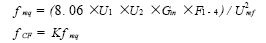
The coefficient Gin is the input gain, F 1-4 is the frequency division that can be obtained by the main clock CLKIN, Uref is the reference voltage, and K is the proportional coefficient.
In the peripheral circuit of ADE7755, the output frequency setting circuit is used to set the output frequency of the CF port, that is, the setting of the meter constant.

Figure 2 Internal block diagram of ADE7755
ADE7755 is a kind of high-precision electricity metering chip. In the case of power frequency, the accuracy reaches 0.1% in the dynamic range of 500: 1. The technical indicators exceed the requirements of the IEC1036 standard.
The only analog circuit is the analog-to-digital conversion circuit, and the other circuits are all digital circuits, which ensures that the chip has sufficient anti-interference ability. Through F1 and F2 real-time output power information, it can directly drive the watt-hour meter counter or directly connect with the single-chip computer.
USB Charger Cable advantage:
For iPhone Cable Charger High Quality Usb Data Line 2.1A Fast Charging USB Cable For Apple Charging Chord For phones Charger
100% Brand new and high quality.Feel smooth, tough and durable,Original quality cable for smart phone.Set bracket, lightning charging solid data line, copper wire specifications, charging 2 core *25*0.1, data 2 core *12*0.1 74 copper wire.

Usb Charger Cable,Usb Charging Cable,Usb Cable Charging Cable,Micro Usb Charger Cable
Dongguan City Leya Electronic Technology Co. Ltd , https://www.dgleya.com