Abstract: A real-time digital video derotation system based on TMS320C6713B is proposed for the rotation of video images caused by detector attitude changes. The system uses the TMS320C6713B to calculate the position of each point after the image is rotated, and then uses the FPGA to perform address mapping to obtain the gray value corresponding to each point after the image is rotated. The experiment proves that the system can eliminate the rotation of the video image in real time, and the image after the de-rotation is clear and stable, meeting the practical application requirements.
Key words: TMS320C6713B; image rotation; affine transformation; APAl50
This article refers to the address: http://
In the infrared camera and aiming process of the airborne TV, the optical system and the imaging device move relative to the carrier due to the roll motion of the TV infrared camera frame, thereby causing image rotation; in many optical sights, infrared pod systems and measurement In the calibration system, in order to eliminate the image rotation caused by the change of the posture of the detector, it is often necessary to perform a real-time inverse rotation transformation on the target image acquired by the optical detector to restore the stable state of the image, so as to accurately automatically image the target image. Identify and track. Considering the real-time nature, the current literature is basically designed with FPGA as the core. Here, a real-time digital video derotation system based on TMS320C6713B is proposed. The affine transformation calculation method is optimized and applied to the system, effectively eliminating the video. The rotation of the image achieves the goal of stabilizing the image.
1 System algorithm design The image is derotated. In fact, according to the rotation angle of the known image, the image is reversely rotated at the same angle, so as to eliminate the influence of image rotation. Therefore, the essence of the image derotation algorithm is the rotation calculation of the image, that is, the original image is rotated by an angle to obtain the target image.
Combined with the practical application, it is assumed that the motion of the carrier causes the global motion existing between two consecutive frames to be represented as translation and rotation around the optical axis, that is, the continuous two frames can be characterized by linear transformation. Therefore, an affine transformation is used to establish an image motion model.
If (X1, Y1), (X2, Y2) are registration points corresponding to each other in the reference frame and the current frame image, respectively, the motion expression between them 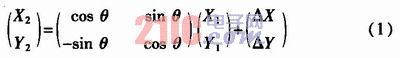
Where θ is the rotation angle ΔX between the registration points, and ΔY is the offset of the registration point in the lateral and longitudinal directions, respectively.
The equation (1) is optimized. Assuming two horizontally adjacent pixels (x, y) and (x+1, y) in the output image, there are corresponding two points in the input image after affine transformation (u1). , v1) and (u2, v2). It is not difficult to derive, the following relationship is established: ![]()
Similarly, assuming two vertically adjacent pixels (x, y) and (x, y+1) in the output image, there are corresponding two points (u1, v1) and (u3) in the input image after affine transformation. , v3), the following relationship is established: 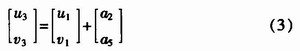
It can be seen from equations (2) and (3) that the transformed two-point coordinate difference in the output image is independent of the position of two adjacent points in the input source image. In other words. As long as the affine transformation is calculated once, the incremental method can be used to find the exact position of all points after the affine transformation. Therefore, the first point of the image uses the complete affine transformation formula ![]()
To perform the calculation, the subsequent points only compute two floating point additions to obtain the exact position of an affine transformation point. After obtaining the exact position, the image gradation is calculated by the nearest neighbor pixel method, and only the calculated coordinate position is rounded off to obtain the integer coordinate value, and the coordinate is used to obtain the gray value of the corresponding point.
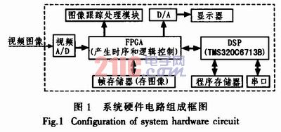
2 system hardware design Real-time digital video derotation system is mainly composed of four parts: video A / D, DSP, FPGA and frame memory. Figure 1 is a block diagram of the system hardware. The principle is that the external image is sampled into a digital image by A/D sampling, and the FPGA writes the image into the frame memory. The DSP calculates the angular velocity value sent by the host computer through the RS-232 serial port, and calculates each point of the new image in the current frame image. The position is sent to the FPGA after the calculation, and the address mapping is performed by FIGA, and then the image is output to the D/A display by the mapped address or sent to the tracking processing module for target tracking recognition and the like.
2.1 TMS320C6713B data processing unit In this scheme, DSP is the core of data processing. It mainly reads the angular velocity information of the image rotation sent by the host computer through the serial port, and performs affine transformation based on the information to obtain the rotated image. Point the coordinates in the original image and write the calculated coordinates to the FPGA. A large number of floating-point operations are required to calculate the precise position of an image, and a DSP with high-speed, high-precision floating-point computing capability is required. The solution uses TI's high-performance floating-point digital signal processor TMS320C6713B. It uses an advanced very long instruction word structure to provide hardware support for single-precision (32-bit) and 64-bit (double-word) IEEE floating-point operations, and 32-bit integer multiply can obtain 32-bit or 64-bit results. It has 8 independent functional units, 2 fixed-point arithmetic logic units (ALUs), 2 floating-point multipliers, and 4 floating-point ALUs. It can execute 8 32-bit instructions per cycle. The internal design has 32 32-bit general purpose registers, a 4 Kbyte L1 high speed program buffer and a 4K byte L1 high speed data buffer, and a 256 Kbyte L2 two level data buffer. This structural design maximizes the parallel computing power of eight functional units, enabling the DSP to operate at up to 2 400 MIPS and up to 1 800 MFLOPS at 300 MHz system clock, which greatly satisfies High-speed data processing requirements.
In addition, the DSP6713B offers a variety of integrated peripherals: multiple reset load modes (BOOT), multi-channel DMA controllers, multi-channel cache serial ports (McBSP), and high-performance external interfaces that interface directly with SDRAM, SBSRAM, or asynchronous memory. Memory Interface (EMIF), which brings great convenience to data processing.
2.2 FPGA Module Unit The solution uses the APAl50 from the second generation of Flash-based programmable device ProASIC Plus from Actel. This family of devices combines the performance of an ASIC (application-specific integrated circuit) with the flexibility of an FPGA, with 150 000 system gates, 6 144 logic cells, embedded 36KB dual-port SRAM and 2 phase-locked loops (PLL) ) kernel, support 3.3 V,
The 32-bit, 50 MHz PCI bus provides up to 150 MHz of external performance with high density, low power, non-volatile and reprogrammable features. Because the ProASIC Plus family of FPGAs is based on Hash technology, the Hash switch is used to hold the internal logic, so no additional components are needed. Since there is no need for a power-on configuration process, it has the feature of working immediately after power-on. In addition, it is highly confidential, and the user can program a multi-bit key to prevent the outside world from reading or changing the configuration of the device.
In the scheme, the APAl50 mainly implements logic control, A/D sampling control, D/A display control, writing images to the frame memory, and completing address mapping of the rotated image and the original image.
3 system software design The system software mainly completes the calculation of the rotation coordinates of the video image. It uses the floating point operation function of TMS320C6713B to realize the assembly program based on CCS3.1 platform. Figure 2 is the basic flow chart, which mainly has the following steps:
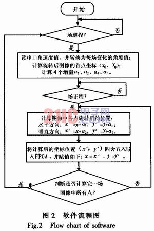
1) When each query arrives in the field, the angular velocity information sent by the host computer is read through the serial port, and the angular velocity is converted into the change amount per 20 ms angle. According to the angle, the complete affine transformation is used to find the coordinates of the first point of the rotated image, and the increments in the horizontal direction and the vertical direction are calculated according to the complete affine transformation formula.
2) When the field forward is queried, the exact position of the current point can be obtained for each line of each point according to the position of the previous point in the original image plus the horizontal direction increment. For the first point of each line, the position of the point in the original image can be obtained by adding the vertical direction increment to the position of the first line of the previous line in the original image.
3) Finally, the obtained image position is rounded off to find the coordinates of the current point in the original image, and finally the coordinates are sent to the FPGA.
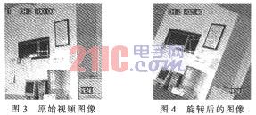
4 Experimental results The image processed in the experiment is 256x256x8 bit, the fixed camera does not move, the arbitrary input angular velocity is 0°~360°/20 ms, the angular velocity can be accurate to 0.1°/20 ms, and the system will surround the image center accordingly. The angular velocity rotates the image. Fig. 3 is an original unrotated image, and Fig. 4 is an image rotated at a speed of 2.4°/20 ms to 30°. It can be seen from Fig. 3 and Fig. 4 that the rotated image is stable and clear.
5 Conclusion This paper proposes a video derotation system based on TMS320C6713B. The system is easy to implement in hardware, with high real-time performance, and the image after rotation is clear and stable, meeting the requirements of engineering applications. In addition, the system is highly scalable and can be used for higher resolution applications such as the 768x576 image derotation system with only minor modifications to the hardware.
Belttt's Battery Charger has intelligent control and management of battery charging process. Multiple safety protection functions. Detailed charging indicator and current value indicator. Applicable to lead-acid batteries and other rechargeable batteries. Use Constant current charge, constant voltage charge, float charge which call three-stage charge.
Battery Charger
Battery Charger,12V Battery Charger,Solar Battery Charger,Car Battery Charger
Guangzhou City Poojin Electronic Technology Co., Ltd. , http://www.inverter-belttt.com