Hand shake is ubiquitous. As long as it is a handheld camera, there are more or less jitter problems. The difference is that everyone's stability is different. This involves the concept of a safe shutter. In simple terms, a safety shutter is the reciprocal of the focal length, that is, the shutter speed reaches or exceeds the safety shutter (the exposure time is less than the exposure time of the safety shutter), which makes it easier to take a clear picture. In the case of long focal length shooting, low light source environment shooting, and macro shooting, since the exposure time is much longer than the exposure time of the safety shutter, anti-jitter technology is needed to compensate, otherwise the results of general photography are not clear. .
This article refers to the address: http://
Digital camera anti-shake technology is generally divided into three categories: electronic anti-shake, lens anti-shake (also known as optical anti-shake), CCD anti-shake. One of the electronic image stabilization is to increase the sensitivity (High ISO), thereby increasing the shutter speed (reducing the exposure time) and making the shutter speed exceed the safety shutter to avoid jitter. This method changes the shutter speed, not only can improve the camera's jitter, but also better capture the moving object, but because of the improved sensitivity, due to the limitations of the components, the corresponding picture noise will increase, affecting the picture the quality of. Table 1 shows the conditional system defined by the International Standards Organization. When the sensitivity (ISO) is increased by one level, the shutter time can be reduced by half. The other is electronic image stabilization, which analyzes the image and processes the edge according to the jitter. It belongs to the back-end processing and does not help the image very much. The lens anti-shake compensates the camera's jitter by the movement of the lens. It consists of a sensor, a microprocessor, a compensating lens control group, and a drive control part. It compensates for the movement of the lens to correct the light deviation caused by the hand shake, as shown in Figure 1. The lens is different and the design is different, but basically it is compensated by the compensation lens group. The CCD anti-shake is placed on a movable stand by the photosensitive component CCD (or CMOS). The sensor senses the camera's jitter, and the microprocessor calculates the corresponding amount of movement. The drive part moves the CCD to achieve the anti-shake purpose. . At present, the general camera anti-shake (CCD anti-shake or optical anti-shake) is not infinitely compensated, generally 2~~3, according to Table 1, suppose the safety shutter 1/125, level 2, shutter speed 1/30 Faster than this speed, it is easy to take clear pictures, and so on, level 3, shutter speed is 1/15. Table 2 shows the comparison table of the three anti-shake modes.
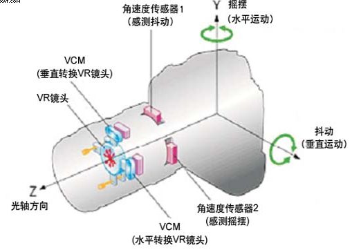
Figure 1 Schematic diagram of optical anti-shake structure
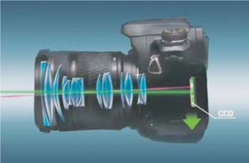
Figure 2 CCD anti-shake diagram
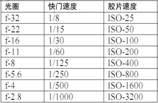
Table 1 Photography combination series

Table 2 Anti-shake mode comparison table
The rapid development of MEMS gyroscopes (Gyro), microelectromechanical systems (MEMS) technology has allowed manufacturers to create complete gyro devices on microchips. The physical phenomenon behind MEMS gyroscopes is the Coriolis effect. As shown in Fig. 3, the micro block is on the rotating surface (ω), and the micro block m will vibrate back and forth, thus generating a vertical Coriolis force of the same frequency. The magnitude of these forces is equal to ±2ωvm and is directly proportional to the angular velocity ω of the overall system. These forces will cause the object of the component shown in Figure 3 to be pushed from one side to the other, and these displacements can be detected as changes in capacitance. At this time, the Gyro needs to use the relevant circuit to detect the oscillation of the capacitor, convert it to a voltage, and then rectify and output a DC voltage. The purpose of this circuit is to convert the rotational speed into a voltage. The main feature of MEMS gyroscopes (Gyro) products is the integration of MEMS mechanical design and manufacturing, mixed-signal ASIC design, and wafer-level packaging technologies to develop gyroscope products with small size, low cost and high efficiency.
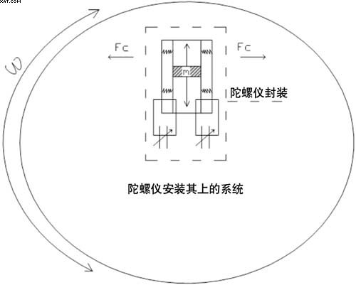
Figure 3 MEMS gyroscope implementation
It can be seen from Fig. 2 that on the 3D surface, the Z-axis has an autofocus function, and the Z-axis movement has no effect on the imaging, and the influence is on the X-axis (PITCH) and the Y-axis (YAW). Figure 4 shows the results of taking pictures at night, no anti-shake and CCD anti-shake. Figure 5 shows the frame of the CCD anti-shake system. The CCD anti-shake is to add a CCD bracket to the lens, and use the stepping motor to drive the X-axis and the Y-axis to make the CCD move to compensate the CCD jitter. MEMS gyroscopes must have X, Y-axis Gyro chips, including internal amplification, low-pass, high-pass filtering, which can greatly reduce the size of the camera. The Gyro signal is connected to the DSP's AD port, and the DSP's AD is 10 bits, which meets the design requirements. The data processing is processed by the DSP of the camera itself, which can reduce a microprocessor (Micro) and reduce the cost. The DSP calculates the ω information transmitted by Gyro, calculates the compensation amount, and drives the X and Y movements through the motor drive circuit to achieve the purpose of compensation. The PI signals of the X-axis and Y-axis are Lens feedback DSP information to correct the coincidence of the CCD and the Lens center to avoid the compensation process exceeding the compensation range of the Lens design.
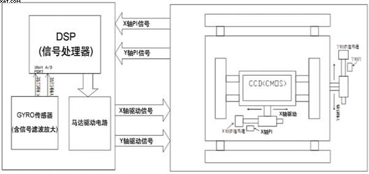
Figure 4 The left photo shows that the anti-shake is not turned on, and the anti-hand shake is turned on the right.

Figure 5 CCD anti-shake system block diagram
Experiments have shown that when the average person holds a camera and takes a picture, the hand-shake frequency is 0~20Hz (source: Japanese version of digital photography magazine 2006/12), and the DSP's sampling frequency of GYRO is set to 500~1KHz to meet the system requirements. Figure 5 is a schematic diagram of the displacement of the jitter, with black being the original position and red being the offset position.
According to the Lens spec, the amount of movement of each phase of the stepping motor (such as 1.44um) is known. It can be known from Equation 3 that the angular velocity of GYRO can be used to calculate the offset of the CCD.
d = f * sinθ ------(1)
When θ < 20° d = f *θ
θ = ∫ω dt -----(2)
θ = Σωi * dt
→ d = f*Σωi * dt -----(3)
d : offset f : focal length ω: angular velocity
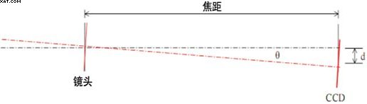
Figure 6 Variation of the dithering path
The CCD anti-shake system uses PID automatic control system (PID is proportional calculus adjustment), as shown in Figure 7, P (proportional) control is Gyro detected jitter proportionally moving CCD, I (integral) control is adjusted for time integration Error, D (differential) is the leading cause of suppression error, such as low frequency power noise compensation. By adjusting the PID parameters, the system can be operated stably and reliably to achieve the design goal. Also consider the impact of components on the system, such as the test error caused by Power noise on Gyro sense, whether the stepper motor can reach the required 1000pps, Gyro's low pass, high pass filter and so on.
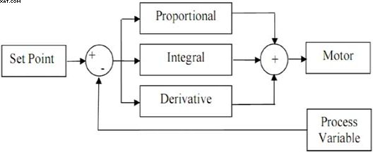
Figure 7 PID block diagram
in conclusion
CCD anti-shake technology can overcome the image blur caused by hand shake, but it is not omnipotent. The current industry compensation standard is 2~3 level of safety shutter. When telephoto or shutter time is too long, when the compensation limit is exceeded, take a photo with a tripod. It is the most effective.
COMPATIBILITY ONLY for iPhone 6, (4.7 inch screen), please
do not confuse it with other versions.
COMPATIBILITY ONLY for iPhone 6 plus (5.5 inch screen), please do not confuse it with other versions.
Warranty: 1 year warranty. For any quality problems, we offer full refund or replacement and you don't need return defective one back to us, 100% working, test 3 times before shipment.Function: Screen replacement to repair cracked/shattered screen. Also solve display/touch issues, dead pixels and wrong color problem.
IPhone 6 Plus Retina LCD Touch,IPhone 6 Plus LCD Touch Screen,IPhone 6 Plus LCD Digitizer
Shenzhen Aokal Technology Co., Ltd. , http://www.aokal.com