OPE-FTT-H208
Installation Manual
Features:
- Mechanical seal: good sealing, can repeat use. Protective level: IP65.
- Laying: outdoor wall-mounting and pole-mounting.
-
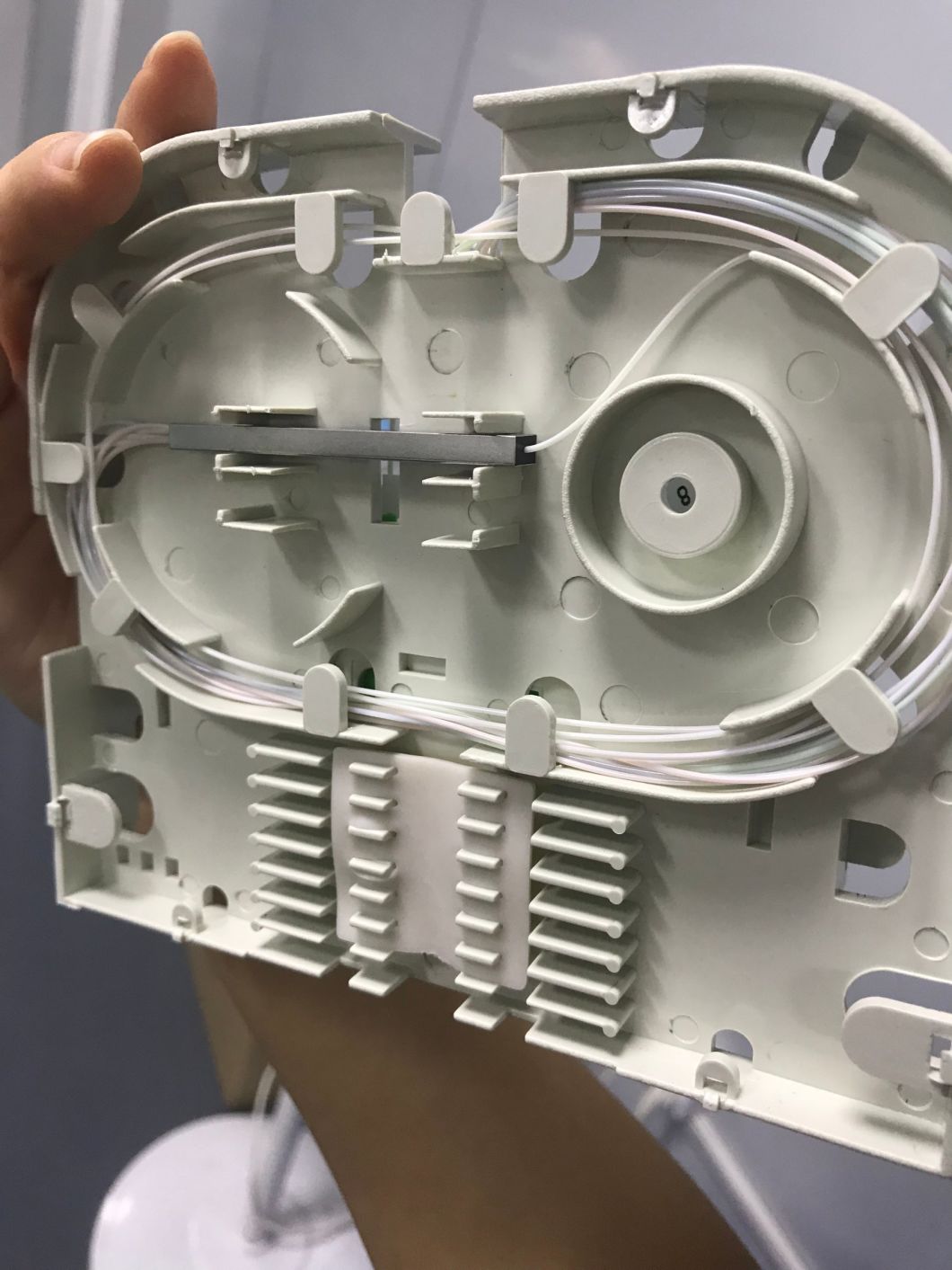
Product Features:Â
- FTTH products, passive optical points wiring special terminal box;
- The box body to scroll type structure, it has the function of guard against theft, large capacity function complete, easy to use;
- Can meet the following Ф 12 cable into, and can meet the figure 8 or Φ 3 cable protective in splice connection;
- Can be installed 1:8 SC or 1:16 LC Mini- splitter;
- LC biggest for 16 core, SC biggest for 8 core.
 Part Name                   Â
| NO. | Name |
| 1 | Base |
| 2 | Splice Tray |
| 3 | Adapter (for customers chose) |
| 4 | Adapter fixing panel |
| 5 | Strengthen the core fixed press block |
| 6 | Stainless steel hose |
| 7 | Stainless steel hose hoops(Fixing cable parts) |
| 8 | Sealing ring |
| 9 | Cover |
| 10 | Lock |
| 11 | Cable enter ports |
| 12 | Hasp |
Operation Instruction:
- Cable stripping
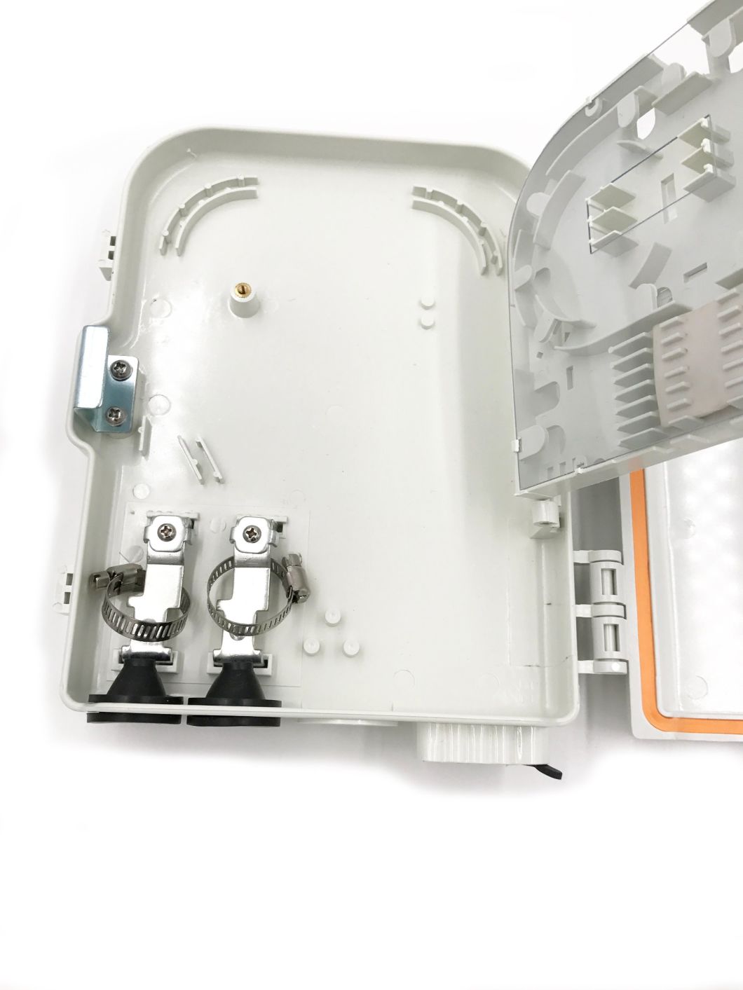
  2,Cable fixing
       Will stripping cable inserted into the hole good fiber optic cable, through the hose hoops and cable strengthen core placed to strengthen the core press block press tightly, and then the cable fixed with stainless steel hose hoops.
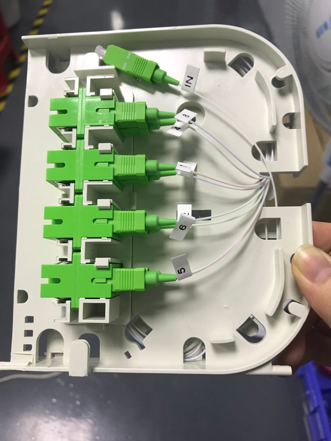
  3,Optical fiber connection
         According to the picture shows to pigtail or splitter (input) welding and welding after the completion of the layout will be in accordance with pictures of optical fiber, pigtail,heat shrinkable protective sleeve and splitter is put to the corresponding position and be fixed, take fiber with protective coat and pigtail end with nylon tie fixed,the heat shrinkable protective sleeve useful rubber cover plate fixed, the splitter used double-sided tape fixed, finally cover the transparent plate.
Part NameÂ
4,Pigtail/path cord
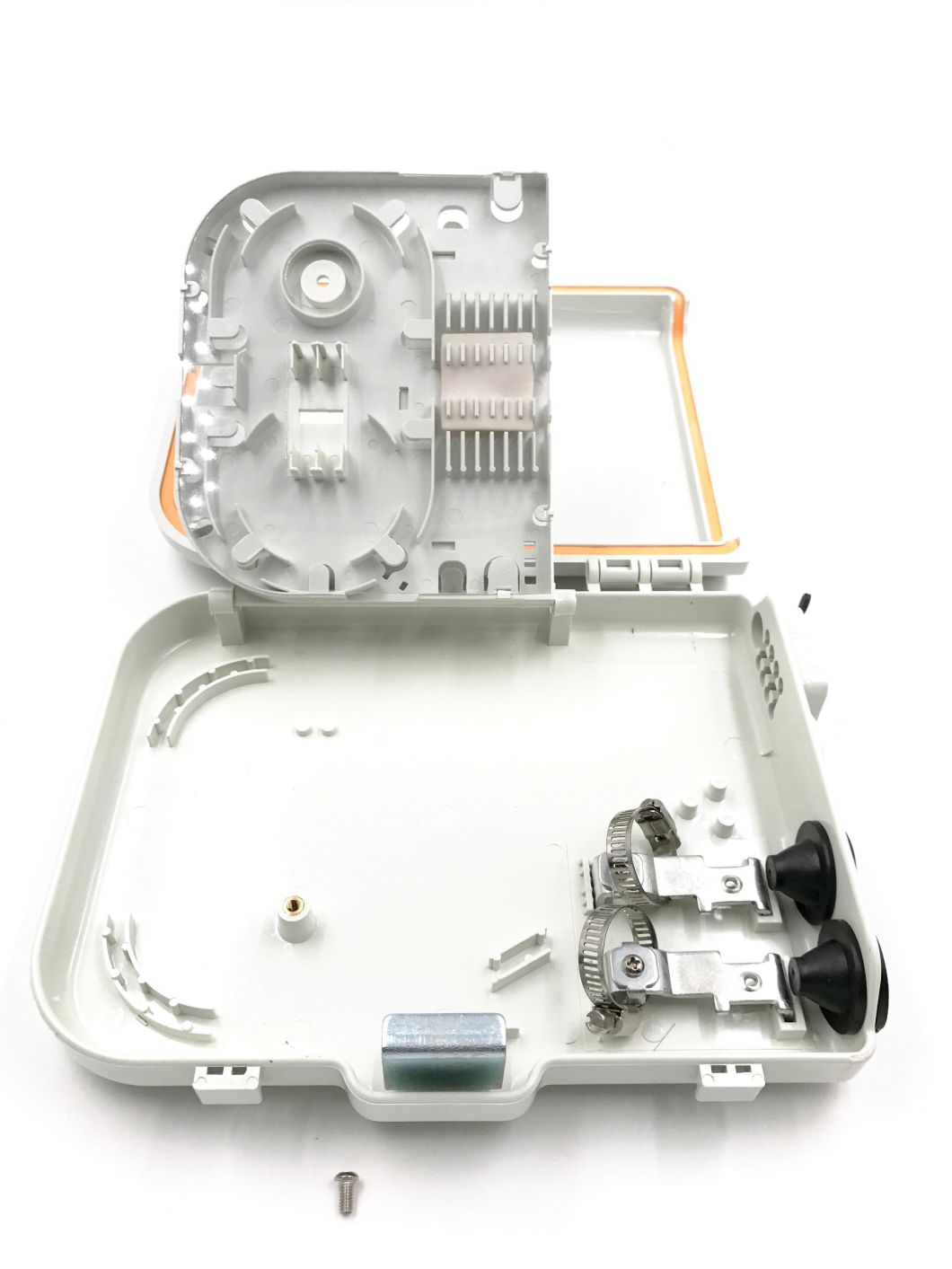
Flip in splice tray, with fixed screw will be fixed in the splice tray.
According to the picture shows will pigtail joint insert adapter, and will put the pigtail tray be fixed.
Will do the path cord or terminal box outlet joint through the fiber outlet hole, the path cord (outlet) joint insert the adapter.
5,Fiber outlet holes sealing
Step1. Path cord (outlet) according to insert the order of the adapter ordinal put corresponding slots;
Step2. Take out path cord (outlet) sealing ring, will do the path cord (outlet) package closely;
Step3. Will do the path cord(outlet) sealing ring from the corresponding pressed into the slots, to the bottom;
Step4. Plug of fiber outlet holes have acted the path cord (outlet ) of the part to cut off;
Step5. Cut the plug will be prepared from terminal box external to the fiber outlet holes into within;
   Â
6,Installation fixing
A.Wall-mounting installatin(standard configuration)
According to your drawings on the wall a crossed punch, and then will plastic expand into flush with metope;
By tapping screws twist into plastic expand, to tapping screws tail and metope 4 mm distance;
Will do the base of lock hole big head the most standard of screw into, and down lock.
----------------------------------------------------FAQ---------------------------------------------------
Q1. Can I have a sample order for this product? What' MOQ of it?
A:Â Yes welcome send sample order for test. MOQ is 1 piece.Â
Â
Q2. What about the lead time?
A:Sample needs 3-5 days, mass production time needs 1-2 weeks.Â
Â
Q3: What' s the payment term
A: We usually use TT(Telegram Transfer) in advance, Western Union. Other payment method
is
negotiable.
Â
Q4. How do you ship the goods and how long does it take to arrive?
A: We usually ship by DHL, UPS, FedEx or TNT. It usually takes 3-5 days to arrive. Airline
and sea shipping
also optional.
Â
Q5: What' s the freight of it?
A: It depends on the order quantity. We have some reliable ship forwarders. We will offer cost
effective method for you.
Â
Q6: Do you offer guarantee for the products?
A: Yes, we offer 1-2 years warranty according to different products.
Â
Q7: What action will you take if there are some product problems?
A: If there are defective ones in the batch of products, we will offer spare ones for.Â
 Passive Optical Points Terminal Box -FTTH
OPE-FTT-H208
Installation Manual
Features:
- Mechanical seal: good sealing, can repeat use. Protective level: IP65.
- Laying: outdoor wall-mounting and pole-mounting.
-
Product Features:Â
- FTTH products, passive optical points wiring special terminal box;
- The box body to scroll type structure, it has the function of guard against theft, large capacity function complete, easy to use;
- Can meet the following Ф 12 cable into, and can meet the figure 8 or Φ 3 cable protective in splice connection;
- Can be installed 1:8 SC or 1:16 LC Mini- splitter;
- LC biggest for 16 core, SC biggest for 8 core.
 Part Name                   Â
| NO. | Name |
| 1 | Base |
| 2 | Splice Tray |
| 3 | Adapter (for customers chose) |
| 4 | Adapter fixing panel |
| 5 | Strengthen the core fixed press block |
| 6 | Stainless steel hose |
| 7 | Stainless steel hose hoops(Fixing cable parts) |
| 8 | Sealing ring |
| 9 | Cover |
| 10 | Lock |
| 11 | Cable enter ports |
| 12 | Hasp |
Operation Instruction:
- Cable stripping
  2,Cable fixing
       Will stripping cable inserted into the hole good fiber optic cable, through the hose hoops and cable strengthen core placed to strengthen the core press block press tightly, and then the cable fixed with stainless steel hose hoops.
  3,Optical fiber connection
         According to the picture shows to pigtail or splitter (input) welding and welding after the completion of the layout will be in accordance with pictures of optical fiber, pigtail,heat shrinkable protective sleeve and splitter is put to the corresponding position and be fixed, take fiber with protective coat and pigtail end with nylon tie fixed,the heat shrinkable protective sleeve useful rubber cover plate fixed, the splitter used double-sided tape fixed, finally cover the transparent plate.
Part NameÂ
4,Pigtail/path cord
Flip in splice tray, with fixed screw will be fixed in the splice tray.
According to the picture shows will pigtail joint insert adapter, and will put the pigtail tray be fixed.
Will do the path cord or terminal box outlet joint through the fiber outlet hole, the path cord (outlet) joint insert the adapter.
5,Fiber outlet holes sealing
Step1. Path cord (outlet) according to insert the order of the adapter ordinal put corresponding slots;
Step2. Take out path cord (outlet) sealing ring, will do the path cord (outlet) package closely;
Step3. Will do the path cord(outlet) sealing ring from the corresponding pressed into the slots, to the bottom;
Step4. Plug of fiber outlet holes have acted the path cord (outlet ) of the part to cut off;
Step5. Cut the plug will be prepared from terminal box external to the fiber outlet holes into within;
   Â
6,Installation fixing
A.Wall-mounting installatin(standard configuration)
According to your drawings on the wall a crossed punch, and then will plastic expand into flush with metope;
By tapping screws twist into plastic expand, to tapping screws tail and metope 4 mm distance;
Will do the base of lock hole big head the most standard of screw into, and down lock.
----------------------------------------------------FAQ---------------------------------------------------
Q1. Can I have a sample order for this product? What' MOQ of it?
A:Â Yes welcome send sample order for test. MOQ is 1 piece.Â
Â
Q2. What about the lead time?
A:Sample needs 3-5 days, mass production time needs 1-2 weeks.Â
Â
Q3: What' s the payment term
A: We usually use TT(Telegram Transfer) in advance, Western Union. Other payment method
is
negotiable.
Â
Q4. How do you ship the goods and how long does it take to arrive?
A: We usually ship by DHL, UPS, FedEx or TNT. It usually takes 3-5 days to arrive. Airline
and sea shipping
also optional.
Â
Q5: What' s the freight of it?
A: It depends on the order quantity. We have some reliable ship forwarders. We will offer cost
effective method for you.
Â
Q6: Do you offer guarantee for the products?
A: Yes, we offer 1-2 years warranty according to different products.
Â
Q7: What action will you take if there are some product problems?
A: If there are defective ones in the batch of products, we will offer spare ones for.Â
Â
1.ANTENK Card Edge Connectors are precision engineered PCB mount connectors developed to mate with the plated fingers of a printed circuit daughter board. Their bifurcated, cantilever contacts are set in a dual readout configuration and they offer a reliable connection for a wide range of PCB thicknesses. ANTENK`s sturdy solder tails with tapers allow easy insertion and rugged durability
Card Slot Connectors Specification:
*Electrical Characteristitics:
Current Rating;0.5A.
Withstanding Voltage:AC500V r.m.s.
Insulation Resistance:1000Megohms Minimum at DC 500V
Contact Resistance:100Miliohms Maximum.
*Mechanical Characteristics:
Mating Cyeles:5000 Insertions.
*Environmwntal:
Operating Temperture:-40°To+60°
*Material:
1.Housing:HI-Temp plastic UL 94V-0 Rated.
2.Contact:Copper Alloy.
3.Shell:SUS.
*Finish :
1u" Gold plated on conatct area,1u" Gold plated on
solder tails, Base Nickel :50u"Min
*Packing:
Number of connectors:750Pcs/REEL

MATERIAL&FINISH
Insulator:PBT Glass Fiber(UL94V-0)
contact:Brass
Contact:Gold-Plated Over Nickel
SPECIFICATIONS
Current Rating:1A AC,DC
Voltage Rating:250V AC,DC
Temperature Range:-40℃ To+105℃
Contact Resistance:20mΩMin
Insulation Resistance:1000MΩ Min
Withstanding Voltage:500V AC/Min
Video Card Connectors,Card Slot Connectors,Card Edge Slot Connector,CF Card Connector, Edge Card Connector,Memory Card Connector,PC Card Connector,SIM Card Connector,Smart Card Connector
ShenZhen Antenk Electronics Co,Ltd , https://www.antenkcon.com