The charger is a device that supplements the electric bicycle battery with electrical energy. It is mainly composed of rectification and filtering circuit, high voltage switch, voltage conversion, constant current, constant voltage and charging control. The purpose of the rectification and filtering circuit is to convert the 220V AC voltage of the mains into a voltage of about 300V DC. Through the high voltage switching circuit and voltage exchange, the low voltage DC voltage required for charging is generated, and then the battery is charged by the charging control circuit.
The two plugs of the charger are respectively a power plug connected to the mains and a charging plug connected to the battery, and the two indicators respectively indicate the power and the state of charge.
Ka3842_lm358 electric car charger circuit
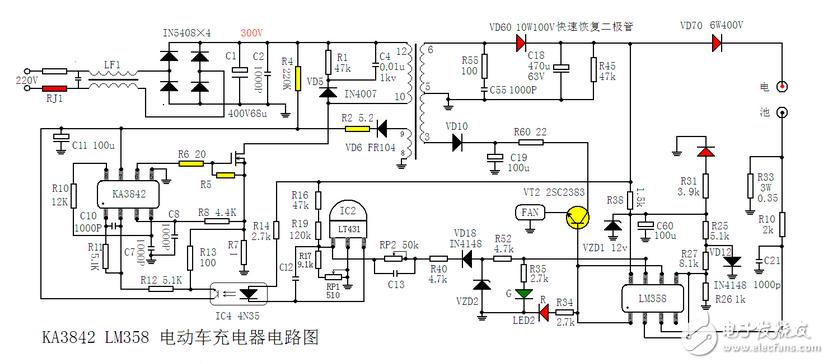
Ka3842_lm358 electric car charger circuit working principle
220V AC is LF1 bidirectional filtering. VD1-VD4 is rectified into pulsating DC voltage, and then filtered by C3 to form a DC voltage of about 300V. The 300V DC voltage is supplied to the 7-pin of the pulse width modulation integrated circuit IC1 through the starting resistor R4. IC1 After the 7-pin gets the startup voltage, (the integrated circuit starts to work when the voltage of the 7-pin is higher than 14V), the PWM pulse of the 6-pin output, and the power switch (field effect) is driven.
VT7 operates in the switching state, and current flows through the S pole-D pole-R7-ground terminal of VT1. At this time, the 8-9 winding of the switching transformer T1 generates an induced voltage. Via VD6, R2 provides a stable operating voltage for pin 7 of IC1, and the external 4-pin oscillating resistor R10 and oscillating capacitor C7 determine the oscillation frequency of IC1.
IC2 (TL431) is a precision reference voltage source. IC4 (optocoupler 4N35) is used to stabilize the charging voltage. Adjusting RP1 (510 ohm semi-adjustable potentiometer) can finely adjust the voltage of the charger. LED1 is the power indicator. This indicator will glow red when the power is turned on.
After VT1 starts working, the output voltage of the secondary 6-5 winding of the transformer is rectified by the fast recovery diode VD60, and the C18 filter obtains a stable voltage (about 53V). This voltage is charged to the battery via diode VD70 (which prevents the battery from flowing back to the charger), and the other through current limiting resistor R38, Zener diode VZD1, filter capacitor C60, for comparator IC3 (LM358) 12V working power supply, VD12 provides reference voltage for IC3, and is divided by R25, R26, R27 and sent to pin 2 and pin 5 of IC3.
During normal charging, the upper end of R33 has a voltage of 0.18-0.2V. This voltage is applied to pin 3 of IC3 via R10, and outputs a high level from pin 1. The high-level signal of the 1-pin output is divided into three outputs. The first drive VT2 is turned on, the heat-dissipating fan starts to work, and the second pass illuminates the red LED in the two-color diode LED2 through the resistor R34. The third input is IC6's 6 feet, at this time 7 feet output low level, the green LED in the two-color LED2 is extinguished, and the charger enters the constant current charging stage.
When the battery voltage rises to about 44.2V, the charger enters the constant voltage charging phase, and the current gradually decreases. When the charging current is reduced to 200MA-300MA, the voltage at the upper end of R33 drops, the voltage of pin 3 of IC3 is lower than 2 feet, the output of 1 pin is low level, the red LED in the two-color LED 2 is extinguished, the transistor VT2 is cut off, the fan Stop running, and IC3's 7-pin output is high. This high level illuminates the green LED in the two-color LED2 through resistor R35 (indicating that the battery is full, it is not really full at this time, actually has one Two hours can be really full), the other way through R52, VD18, R40, RP2 reaches the 1 pin of IC2, so that the output voltage is reduced, the charger enters the trickle charge phase of the 200MA-300MA (floating charge), changing the resistance value of RP2 can Adjust the charger's transition from constant current charging state to choke charging state (200-300MA).
Breaker Rcbo,Rcbo Protection,Leakage Protection Rcbo,Leakage Protection Switch
ZHEJIANG QIANNA ELECTRIC CO.,LTD , https://www.traner-elec.com