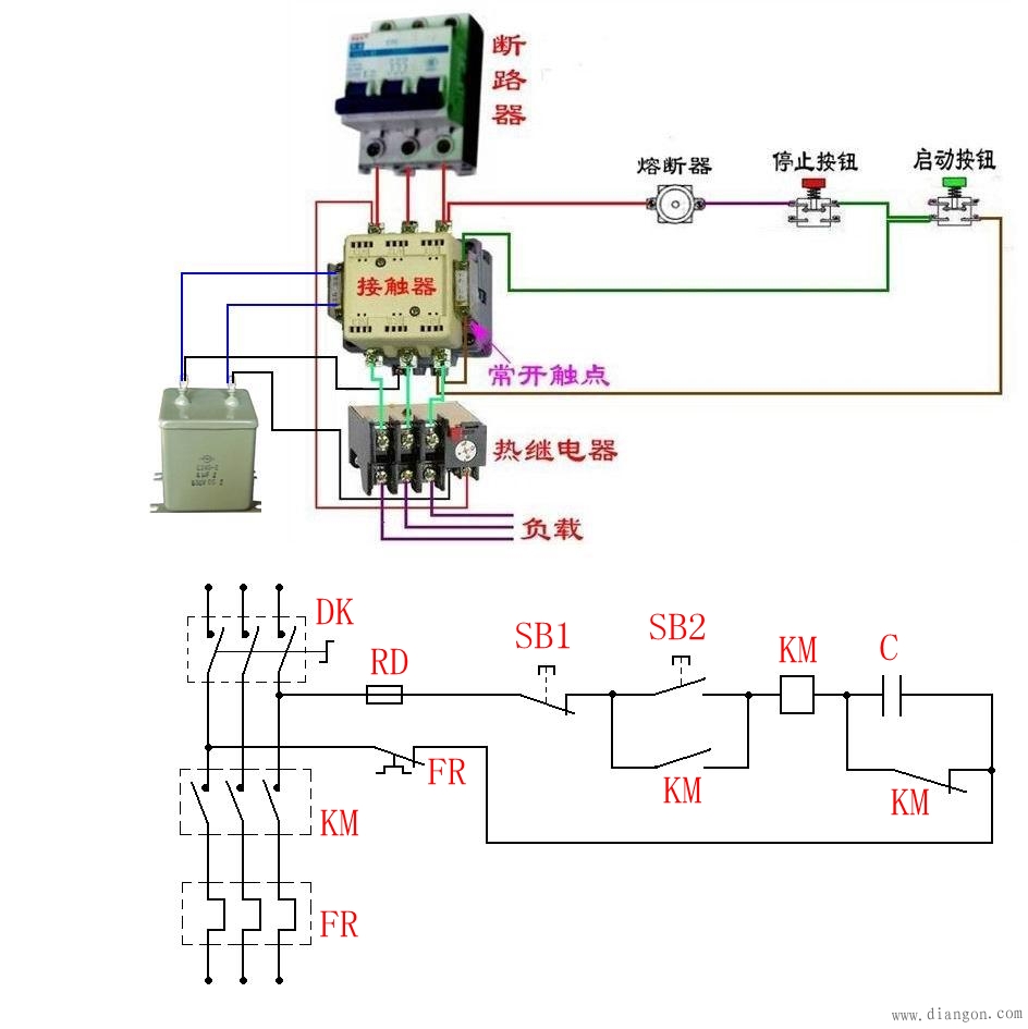
To enable a motor to rotate in both forward and reverse directions, two contactors—KM1 and KM2—are commonly used to reverse the phase sequence of the three-phase power supply connected to the motor. However, it's crucial that these two contactors cannot be activated simultaneously, as this could lead to a dangerous short circuit. To prevent such an issue, a reliable interlocking mechanism must be implemented in the circuit.
The diagram shown illustrates a control circuit for a motor that uses both button and contactor interlocking to ensure safe forward and reverse operation. Here’s a breakdown of how the system works:
Forward Start:
- First, close the air switch QS to connect the three-phase power supply.
- Press the forward start button SB3. This energizes the KM1 contactor, which then locks itself in place via its auxiliary contacts. The main contact closes, allowing the motor to run in the forward direction with the phase sequence L1, L2, L3.
Reverse Start:
- Again, close the air switch QS to connect the power supply.
- Press the reverse start button SB2. This energizes the KM2 contactor, which also locks itself using its own auxiliary contacts. The main contact closes, reversing the phase sequence to L3, L2, L1, causing the motor to rotate in the reverse direction.
Interlocking Mechanism:
Interlocking is essential to prevent both contactors from being energized at the same time. There are two types of interlocking used in this circuit:
- Contactor Interlock: The coil circuit of KM1 includes a normally closed auxiliary contact from KM2, and vice versa. When KM1 is energized, its auxiliary contact opens, cutting off the power to KM2. This ensures that only one contactor can be active at a time, preventing a short circuit.
- Button Interlock: The buttons SB2 and SB3 have both normally open and normally closed contacts. These are wired so that pressing SB2 energizes KM2 while de-energizing KM1, and pressing SB3 does the opposite. If both buttons are pressed at once, neither contactor will activate, further ensuring safety.
Additional Notes:
- Once the motor is running in one direction, you don’t need to press the stop button. Simply pressing the opposite direction button (e.g., reverse if running forward) will change the direction without stopping the motor first.
- The thermal relay FR provides overload protection for the motor. It automatically disconnects the power if the motor draws too much current for an extended period.
Wiring and Troubleshooting:
Before testing the circuit, it's important to check the wiring carefully. Ensure that the main circuit connections are correct and that the phase sequence of the motor can be reliably reversed when the contactors operate. Also, during testing, always disconnect the motor wiring first to avoid accidental damage or injury.
Common Faults and Solutions:
- Motor Doesn't Start: Check if the fuse FU is blown, if the thermal relay FR has faulty contacts, or if the normally closed contact of SB1 is damaged. Another possible cause is incorrect button interlocking wiring.
- Contactors Don't Engage: This might happen if the interlocking contacts are incorrectly connected. For example, if the normally closed contact is mistakenly used to lock the contactor, it may prevent it from engaging properly.
- No Self-Locking: This usually indicates a wiring error in the self-locking contacts. Make sure that the auxiliary contacts are correctly connected to maintain the contactor’s activation after the start button is released.
Connection Tips:
A standard three-phase contactor typically has eight terminals: three input points, three output points, and two control points. The outputs and inputs are matched, making it easy to identify. To add a locking function, you can connect the output terminal to the control terminal. Understanding the principle of the AC contactor is key—when the coil is energized, it generates an electromagnetic field that pulls the contacts together. Once power is removed, the contacts return to their original state. Knowing this helps in identifying the coil terminals (usually located at the bottom) and distinguishing between normally open and normally closed contacts. Always check the voltage rating (220V or 380V) before connecting the circuit.

Receiver Supplies,Dynamic Receiver supply,Cordless Telephone Round Receiver,Dynamic Receiver for Telephone
Gaoyou Huasheng Electronics Co., Ltd. , https://www.yzelechs.com