Power is often the most overlooked part of our circuit design process. In fact, as an excellent design, power supply design should be very important, which greatly affects the performance and cost of the entire system.
Here, only the capacitor usage in the board power supply design is described. This is often the most overlooked place in power supply design. Many people engage in ARM, engage in DSP, and engage in FPGA. At first glance, it seems to be very high, but it may not be able to provide a cheap and reliable power solution for their own systems. This is also a major reason why our domestic electronic products are rich in functions and poor in performance.
1 important parameters of the capacitor
Ok, let's get back to you. Let's talk about capacitors first. First of all, there is a general understanding of the capacitor brand. The domestic capacitors on the market include three-ring capacitors, Fenghua capacitors, etc., the YAGEO capacitors of Taiwan enterprises (ie, Guoju Capacitor), and foreign imported brands such as TDK capacitors, SAMSUNG capacitors and MURATA capacitors. They are all well-known brands.
Most of the concept of capacitors still stays in the ideal capacitor stage. It is generally considered that the capacitor is a C. I don't know if there are many important parameters for the capacitor. I don't know how a 1uF ceramic capacitor is different from a 1uF aluminum electrolytic capacitor.
The actual capacitance can be equivalent to the following circuit form:
C: Capacitance value. Generally, it is measured at 1 kHz, 1V equivalent AC voltage, DC bias is 0V, but there are many environments where capacitance measurement is different. However, it should be noted that the capacitance value C itself will change with the environment.
ESL: Capacitance equivalent series inductance. The pin of the capacitor is inductive. Insensitive to low frequency applications, so it can be ignored. When the frequency is high, consider this inductor. For example, a 0.1uF chip capacitor in a 0805 package has a 1.2nH inductance per pin, then the ESL is 2.4nH. It can be calculated that the resonant frequency of C and ESL is about 10MHz. When the frequency is higher than 10MHz, the capacitance is Inductive characteristics.
ESR: Capacitance equivalent series resistance. No matter which capacitor has an equivalent series resistance, when the capacitor operates at the resonant frequency, the capacitive reactance and inductive reactance are equal in magnitude, so it is equivalent to a resistor. This resistor is ESR. There are big differences due to different capacitor structures. Aluminum electrolytic capacitors ESR generally range from a few hundred milliohms to several euros, ceramic capacitors are typically tens of milliohms, and tantalum capacitors are between aluminum electrolytic capacitors and ceramic capacitors.
Let's take a look at the frequency characteristics of some X7R ceramic capacitors:
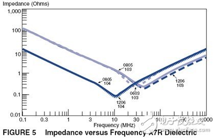
Of course, there are many capacitor-related parameters, but the most important ones in design are C and ESR.
Here is a brief introduction to the three capacitors we commonly use: aluminum electrolytic capacitors, ceramic capacitors and tantalum capacitors.
1) The aluminum capacitor is made by etching the aluminum foil groove and then sandwiching the insulating layer, and then dip the electrolyte solution. The principle is chemical principle. The capacitor charge and discharge depends on the chemical reaction, and the response speed of the capacitor to the signal is affected by the electrolyte. The moving speed limitation of the charged ions in the medium is generally applied to the filtering of the lower frequency (below 1M). The ESR is mainly the sum of the equivalent resistance of the aluminum crucible and the electrolyte, and the value is relatively large. The electrolyte of the aluminum capacitor will gradually evaporate, resulting in a decrease or even a failure of the capacitor, and the evaporation rate will increase as the temperature increases. For every 10 degrees increase in temperature, the life of the electrolytic capacitor is halved. If the capacitor can be used for 10,000 hours at room temperature of 27 degrees, only 1250 hours can be used in a 57 degree environment. Therefore, the aluminum electrolytic capacitor should not be too close to the heat source.
2) The storage of the ceramic capacitor is based on the physical reaction, so it has a high response speed and can be applied to the upper G. However, ceramic capacitors vary greatly depending on the medium. The best performance is the capacitor of C0G material, the temperature coefficient is small, but the dielectric constant of the material is small, so the capacitance cannot be made too large. The worst performance is the Z5U/Y5V material. This material has a large dielectric constant, so the capacitance can be tens of microfarads. However, this material is affected by temperature and DC bias (DC voltage will cause the material to be polarized, resulting in reduced capacitance). Let us look at the C0G, X5R, Y5V three material capacitors affected by the ambient temperature and DC operating voltage.
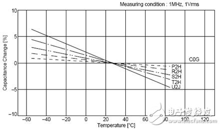
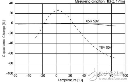
It can be seen that the capacitance of C0G does not change with temperature, and the stability of X5R is slightly worse. When the material of Y5V is 60 degrees, the capacity becomes 50% of the nominal value.
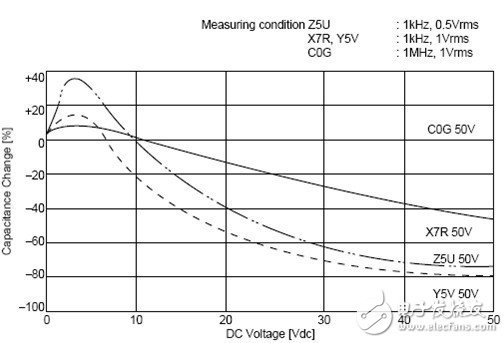
It can be seen that the 50V withstand voltage Y5V ceramic capacitor has a capacity of only 30% of the nominal value when applied at 30V.
Ceramic capacitors have a big drawback, which is fragile. So you need to avoid bumps and try to stay away from the board where the deformation is easy.
3) Tantalum capacitors are like a battery in principle and structure. The following is a schematic diagram of the internal structure of the tantalum capacitor:
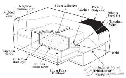
Tantalum capacitors have the advantages of small size, large capacity, fast speed, low ESR, and the price is relatively high. The size of the tantalum capacitor and the pressure resistance are determined by the size of the raw material powder particles. The finer the particles, the larger the capacitance, and the thicker the Ta2O5 if a larger pressure is required, which requires the use of larger particles. Therefore, it is very difficult to obtain a tantalum capacitor with a high withstand voltage and a large capacity. Another place where tantalum capacitors need to be noticed is that tantalum capacitors are easier to break down and have short-circuit characteristics, and have poor surge resistance. It is very likely that a short circuit will occur due to a large instantaneous current causing the capacitor to burn out. This should be considered when using ultra-capacitance tantalum capacitors (such as 1000uF tantalum capacitors).
It can be seen from the above that different capacitors have different applications, and the higher the price, the better.
2 The role of the capacitor in the power supply design
In power supply design applications, capacitors are primarily used for filtering and decoupling/bypass.
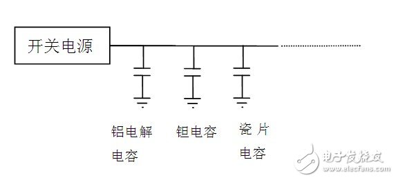
Filtering mainly refers to the noise except filter, and decoupling/bypassing (one, decoupling effect in the form of bypass, and later replaced by "decoupling") is to reduce the external noise interference of the local circuit. Many people tend to confuse the two. Let's look at a circuit structure:
The switching power supply in the figure supplies power to A and B. After passing through C1, the current passes through a PCB trace (temporarily equivalent to an inductor. Actually, the theoretical analysis of this equivalent is wrong, but for the sake of understanding, this equivalent is still used.) Separate the two ways separately Supply A and B. The ripple from the switching power supply is relatively large, so we use C1 to filter the power supply to provide a stable voltage for A and B. C1 needs to be placed as close as possible to the power supply. Both C2 and C3 are bypass capacitors that act as decoupling. When A needs a large current at a certain moment, if there is no C2 and C3, the voltage at the A terminal will become lower due to the inductance of the line, and the voltage at the B terminal is also reduced by the voltage at the A terminal, so the partial circuit The current change of A causes the power supply voltage of the local circuit B, thereby affecting the signal of the B circuit. Similarly, the current change of B also interferes with A. This is the "common path coupling interference."
After adding C2, when the local circuit needs an instantaneous large current, the capacitor C2 can temporarily supply current to A. Even if the common part of the inductance exists, the voltage at the A terminal will not drop too much. The impact on B will also be much reduced. Therefore, the current bypass acts as a decoupling.
The general filtering mainly uses large-capacity capacitors, and the speed requirement is not very fast, but the capacitance value is required to be large. Aluminum electrolytic capacitors are generally used. In the case of a small inrush current, it is better to use a tantalum capacitor instead of an aluminum electrolytic capacitor. From the above example, we can know that as a decoupling capacitor, it is necessary to have a fast response speed to achieve the effect. If the partial circuit A in the figure refers to a chip, then the decoupling capacitor should use a ceramic capacitor, and the capacitor should be as close as possible to the power supply pin of the chip. If "partial circuit A" refers to a functional module, ceramic capacitors can be used. If the capacity is not enough, tantalum or aluminum electrolytic capacitors can be used (provided that each chip in the functional module has a decoupling capacitor - ceramic capacitor) ).
The capacity of the filter capacitor can often be found in the data sheet of the switching power supply chip. If the filter circuit uses electrolytic capacitors, tantalum capacitors, and ceramic capacitors at the same time, the electrolytic capacitor is placed closest to the switching power supply, which protects the tantalum capacitor. The ceramic capacitor is placed behind the tantalum capacitor. This will give you the best filtering results.
Decoupling capacitors need to meet two requirements, one is capacity requirements and the other is ESR requirements. That is to say, a 0.1uF capacitor decoupling effect may not be as good as two 0.01uF capacitors. Moreover, the 0.01uF capacitor has a lower impedance in the higher frequency band. If a 0.01uF capacitor can meet the capacity requirement in these bands, it will have a better decoupling effect than the 0.1uF capacitor.
Many high-speed chip design instruction manuals with more pins will give the power supply design requirements for decoupling capacitors. For example, a 500-pin BGA package requires a 3.3V power supply with at least 30 ceramic capacitors, and several large ones. Capacitor, the total capacity should be more than 200uF.
Solar technology will become one of the future green energy technologies. Solar or photovoltaic (PV) is increasingly used in China. In addition to the rapid development of government-supported photovoltaic power plants, private investors are also actively building factories and planning to put them into production worldwide. Solar components.
Product model: Photovoltaic Cable
Conductor cross section: photovoltaic cable
Many countries are still in the learning phase. There is no doubt that in order to get the best profit, companies in the industry need to learn from countries and companies that have years of experience in solar applications.
Building a cost-effective, profitable photovoltaic power plant represents the most important goal and core competencies of all solar manufacturers. In fact, profitability depends not only on the efficiency or high performance of the solar modules themselves, but also on a range of components that appear to be not directly related to the components. However, all of these components (such as cables, connectors, junction boxes) should be selected based on the long-term investment objectives of the tenderer. The high quality of the selected components avoids the inability of the solar system to be profitable due to high maintenance and maintenance costs.
Photovoltaic Cable
Photovoltaic Cable,Solar Photovoltaic Cable,Special Photovoltaic Cable,Photovoltaic Pv Cable
Jiangsu QiSheng Cable Co., Ltd. , https://www.shuaihe-cable.com