0 Preface
In this paper, the lead-acid battery used in the intelligent controller of the mine permanent magnet operating mechanism feed switch has many problems such as overcharging, insufficient charging, battery overheating and slow charging speed in the charging process, and proposes a kind of atmega16 single chip as the core. Smart charger design. The model PID control algorithm based on sugeno reasoning is adopted to improve the charging speed of the charger, reduce the battery loss, and realize the intelligent control of the charging process of the lead-acid battery.
At present, the intelligent controller of the mine permanent magnet operating mechanism feed switch uses a lead-acid battery as a backup power source. The traditional lead-acid battery charging method has constant current limiting voltage charging and constant voltage current limiting charging, but the charging effect is not very satisfactory. On the one hand, the charging time of these methods is too long, and the temperature rise is too fast. On the other hand, there are overcharge and undercharge in the charging process. Expert research shows that the lead-acid battery charging process has the greatest impact on its life, and over-charging, insufficient charging and temperature rise are the main causes of battery failure.
Based on the above reasons, based on the charging characteristics of the battery, the system uses the ç…³ugeno reasoning based PID control algorithm to design a smart charger with atmega16 microcontroller as the core, which can collect the current, voltage, temperature and other simulations in the battery charging process in real time. The amount is so that the charging is always performed at an optimum state, achieving an efficient, fast, and non-destructive charging process.
1 system overall structural design
The system selects the atmega16 microcontroller produced by ATMEL as the core control chip. The overall structure includes: power module, charging main circuit module, analog detection module, display and alarm module and IGBT drive module. The overall structure of the system is shown in Figure 1.
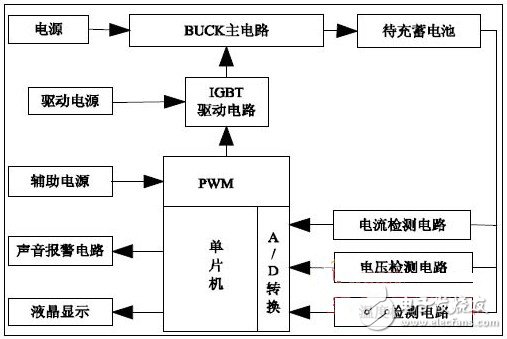
During the charging process, the MCU collects the current, voltage and temperature analog quantities in the battery charging process in real time, converts the above analog quantity into digital quantity through its internal A/D converter, and judges whether the battery has overvoltage or overcurrent. And over temperature and other faults. In the event of a fault, the microcontroller immediately turns off the IGBT and sounds an audible and visual alarm. If the detection is normal, the modulo PID control algorithm based on the sugeno inference is used to generate the PWM pulse of the corresponding duty cycle to control the IGBT switch, and the battery is charged through the BUCK circuit.
2 system hardware circuit design
2.1 charging main circuit design
The charging main circuit is actually a BUCK converter, and the BUCK circuit belongs to a step-down chopper circuit. The main circuit of charging is shown in Figure 3. The IGBT, the diode, the inductor L1 and the capacitor C10 form a BUCK circuit, and the 220V mains is stepped down by a transformer, and is used as a DC charging power source by rectification bridge rectification and EMI smoothing filtering. During the working process, a high-level pulse of the PWM control signal appears to turn on the IGBT, and the current of the inductor L1 is continuously increased, and the capacitor C10 is stored and the battery is charged. At this time, the freewheeling diode is turned off due to the reverse bias. When the PWM signal is low, the IGBT is turned off, the inductor L1 maintains the original current direction, and the freewheeling diode forms a charging loop, which uses the energy stored in L1 and C10 to charge the battery.
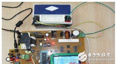
Figure 2 charger physical map
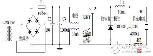
Figure 3 charging main circuit
2.2 Analog Detection Module
2.2.1 Voltage detection circuit design
The voltage detection circuit uses a linear optocoupler HCNR201 to isolate the noise signal from the microcontroller system. The voltage detection circuit is shown in Figure 4.
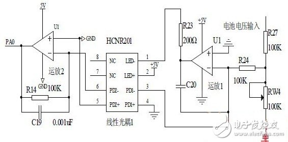
Figure 4 voltage detection circuit
During the normal charging process, the battery terminal voltage Ubat varies from 9V to 15V, and the detection voltage of the single-chip microcomputer ranges from 0 to 5V. Therefore, the voltage across the battery is divided by R27 and Rw4, and the resistance of Rw4 is adjusted. To limit the input voltage of op amp 1 so that it always stays at 0-5V. Resistor R24 ​​controls the magnitude of the primary op amp input bias current. C20 acts as a feedback and filters out the glitch in the circuit to avoid HCNR201 illumination. The diode LED is subject to an unexpected shock. R23 can control the intensity of the LED's illumination, which plays a role in controlling the channel gain. Operational amplifier 2 and resistor R14 convert the output current signal of the linear optocoupler HCNR201 into an output voltage signal and send it to the microcontroller.
The LED Indicator is a device that monitors the operation or position of an electrical device with light. The indicator light is usually used to reflect the working state of the circuit (with or without electricity), the operating state (running, outage or test) of the electrical equipment, and the position status (closed or disconnected).
In our company,mainly have eight series(as follow):
AD22-22DS LED Indicator
AD22-4SMD LED IndicatorAD16 LED Indicator
AD22-22MSD Buzzer
AD22-30DS LED Indicator
AD22-DAV Current Voltage Indicator
AD22-DAM Current Indicator
AD22-DVM Voltage Indicator
LED Indicators,LED Indicator Light,LED Indicator Lamp,LED Indicator Bulbs
Ningbo Bond Industrial Electric Co., Ltd. , https://www.bondelectro.com