The straightforward charger detailed in this article can automatically charge batteries below 24V. It boasts a maximum charging current of up to 2.5A, featuring both constant current charging and automatic cutoff functionality upon full charge. This design ensures safety and efficiency while providing optimal performance for various battery types.
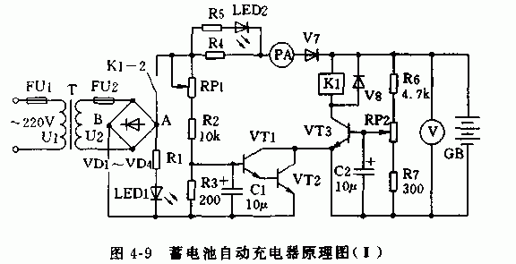
As illustrated in Figure 4-9, the schematic diagram of the automatic charger demonstrates how the 220V AC mains voltage is stepped down by the transformer T to produce the secondary voltage U2. The diodes VD1 through VD4 rectify this AC voltage into a pulsating DC output. The positive terminal at point A passes through the relay's normally closed contacts K1-2, resistor R4, an ammeter PA, transistor VT1, and finally reaches the battery GB. From there, it flows via transistor VT2 to the negative terminal at point B, completing the charging circuit for the battery GB. By adjusting the potentiometer RP1, one can control the base potentials of transistors VT1 and VT2, thereby regulating the collector current Icb of VT2, which determines the charging current. Given that the battery terminal voltage reflects its charging status, let’s take a 12V nominal voltage battery as an example. When the battery voltage increases to (12/2)*2.5=15V, transistor VT3 saturates, energizing relay K1. This action opens the normally closed contact K1-2, breaking the charging circuit and halting the charging process. Adjusting RP2 sets the upper limit for the battery's full-charge cutoff threshold.

fiber optic connector FOC1,optic fiber connector FOC1,SC Fiber Optic Connector FOC1
Wenzhou Hesheng Electronic Co., Ltd. , https://www.heshengelec.com