1 Introduction
The automatic temperature adjustment phototherapy system is a medical physiotherapy instrument. Its principle is to use a single-chip microcomputer to control the thyristor to control the laser output device under high pressure for physical therapy. The laser output device works at the same time to perform real-time temperature detection and use detection The temperature condition reached determines the conduction state of the thyristor, achieves the purpose of changing the output power of the laser output device, and obtains the best therapeutic effect.
According to the above characteristics, this article selects the single bus digital temperature sensor DS18B20 for temperature acquisition, and introduces the program code using DS18B20. In order to make the output power of the thyristor change continuously and evenly, this paper designs a programming method that uses external interrupt and timer interrupt to realize the thyristor phase shift triggering, which can meet the needs of uniform and sensitive change of the intensity of the treatment light.
2 Introduction of thermostat phototherapy system
2.1 Introduction to system structure
The system consists of 5 parts: CPU processing unit, keyboard input unit, LCD display unit, temperature measurement unit, and thyristor control laser output unit.
The CUP processing unit runs the system program to schedule all tasks. The keyboard is used to input system setting parameters and control status mode selection. The LCD provides a good operating interface for the system. The temperature measurement unit is responsible for real-time detection of the temperature of the laser output device and controllable. The silicon control output unit controls the output of the laser output device for the set parameters and the detected temperature. This article will introduce in detail the hardware and software design of the temperature measurement unit and the thyristor control unit.
2.2 System program flow introduction
The procedure of this medical system is as follows: the system first initializes the data. The initialization here mainly includes the setting of timers and external interrupts. After the initialization is completed, the external interrupts are turned on. Then the system performs temperature collection, based on the collected temperature and the system settings parameters. Determines the timer timing parameter, which directly determines the size of the conduction angle when the phase shift triggers the thyristor. Then the system collects the temperature again, selects the timer timing time parameter, and cycles in turn.
During the system's cyclic working process, various operating parameters of the system can be changed manually by keys. The operating parameters directly affect the selection of timer parameters that control the conduction angle of the thyristor. The main flow diagram of the system is shown in Figure 1 (a). When the system is cyclically executed, the external zero-crossing pulse signal will cause the system to enter an external interrupt service routine, which in turn controls the conduction of the thyristor.
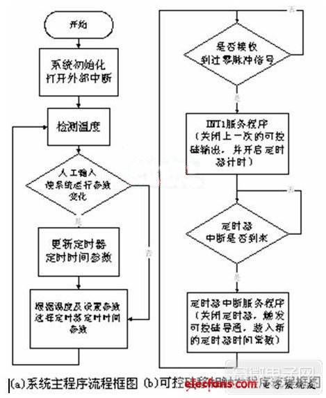
Figure 1: Flow chart of the system program
3 Introduction to temperature measurement unit
Thermocouples or platinum resistors require amplification circuits and A / D conversion to achieve temperature signal acquisition. In order to simplify the system hardware design, the single-bus digital temperature sensor DS18B20 produced by DALLAS was selected.
The "one-line" bus interface provided by DS18B20 requires only one port for communication; the temperature measurement range is -55 ~ + 125 ℃, and the accuracy is ± 0.5 ℃ within the range of -10 ~ + 85 ℃; the temperature is 9 ~ 12 digits Measured out, the resolution is 0.0625 ℃, the accuracy meets the requirements of the medical phototherapy system; meanwhile, the DS18B20 is packaged in an ultra-small μSOP, which is very small and can be directly applied to the front end of the laser. Because the "one-line" bus interface provided by the DS18B20 requires only one port to communicate with the CPU, on the hardware, a port P2.0 of the microcontroller AT89C52 is used to connect to the DQ pin of the DS18B20.
3.1 Working principle and procedure of DS18B20
Before reading and writing to the DS18B20, the CPU first sends out a reset pulse with a low-level signal with a minimum pulse width of 480 μs; then the CPU releases the single bus to make it in the receiving state. The single bus is pulled to a high level through a pull-up resistor. When the DS18B20 detects the rising edge of the I / 0 terminal, it waits for 15-60μs, and then sends a response pulse (60-240μs low level signal) to the main CPU. The initialization subroutine is:
bit init_18b20 (void);
{bit presence; // Used to save DS18b20 response signal to CPU
DQ = 0; // Low level of reset pulse
delay_20us (25); // delay 500us
DQ = 1; // Reset pulse high level
delay_20us (4); // Delay 80us
presence = DQ; // Save the state of DQ
delay_20us (20); // Delay 400us
return (presence); // Return the status of DQ}
When the main CPU pulls the I / O line from high level to low level, and the hold time is greater than 1μs, it is regarded as the beginning of a read cycle. The output data of DS18B20 is valid within 15μs after the falling edge of the read timing. During this period, the main CPU should release the I / O line to make it in the read-in state to read the output data of DS18B20. After 15μs, the read sequence ends and the I / O line goes high through the pull-up resistor. It usually takes at least 60μs to read one bit of data, and a recovery period of at least 1μs between the two bits of data. The subroutine to read the temperature byte is:
byte read_byte (void)
{byte i; // Variable is used for loop self-add
byte value = 0; // Temporary variable for shift operation
for (i = 8; i》 0; i--)
{value》》 = 1;
DQ = 0;
NOP_1uS; // The no-operation macro with a 1us delayed no-operation macro
DQ = 1;
NOP_1uS; NOP_1uS; NOP_1uS;
if (DQ) value | = 0x80;
delay_20us (3); // delay 60us
} return (value); // return the right byte}
When the CPU pulls the I / O line from a high level to a low level, it starts as a write cycle. There are two types of write timing: write 1 timing and write 0 timing. Write 1 or write 0 must be kept at least 60μs, and there is at least 1μs recovery period between two write cycles. DS18B20 samples within 15-6Oμs after the I / O line goes low.
If the I / O line is high, it is considered that a bit is written; otherwise, it is considered that a bit is written. When the main CPU starts writing 1 cycle, it must pull the I / O line to a low level, then release it, and pull the I / O line to a high level within 15 μs. When the main CPU starts to write 0, it also pulls the I / O to low level and keeps it for 60us. The subroutine for writing bytes is:
void write_byte (char val) // "val" pass the byte to be written
{unsigned char i; // Variable is used for self-increment
for (i = 8; i》 0; i--)
{DQ = 0; NOP_1uS; NOP_1uS;
DQ = val & 0x01;
delay_20us (5); // Delay time 100us
DQ = 1; val = val / 2; // shift one bit to the right
} delay_20us (5); // Delay time 100us}
Each operation to access the DS18B20 starts with initializing the device, and then issues ROM commands and function commands. Initializing the device will cause the host to receive an answer signal. The ROM command is related to the unique 64-bit ROM code of each slave device, allowing the host to specify the operation of a slave device when connecting multiple slave devices on the 1-Wire bus. These commands also allow the master to detect how many slave devices and their device types are on the bus, or whether any devices are in an alarm state.
This system is a single-point system with only one temperature sensor. By using the skip ROM (SKIP ROM) command, the host does not have to send a 64 b serial number, which saves a lot of time. After the ROM command, the host can issue the specified function command (temperature conversion, read scratchpad, etc.) to complete the operation. The procedure for reading the temperature in this system is:
unsigned int Read_Temperature (void)
{unsigned char a, b; // variable for storing temperature data
if (init_18b20 () == 0)
{write_byte (0xCC); // Send Skip ROM command
write_byte (0x44); // Send temperature conversion command
delay_20us (1);
if (init_18b20 () == 0)
{write_byte (0xCC); // Send Skip ROM instruction
write_byte (0xBE); // Send read temporary register command
a = read_byte (); // Read the temperature data of the lower eight bits
b = read_byte (); // Read the temperature data of the upper eight bits
temperature = ((b * 256 + a) / 16); // Calculate the decimal temperature value
}} return (temperature);}
Desk Table Mini Vacuum Cleaner, this vacuum cleaner has both blow and suction function. It can help clean the table or office desk very well. As a Wet Dry Vacuum Cleaner, it also can help clean some water on the table or desk.
With strong suction or blow function, this handheld Mini Vacuum Cleaner can clean the dust or other small things very easily. Small body, this make it can be stored everywhere you like. You don`t need to worry it will take large space.
Handheld Vacuum Cleaner: This mini vacuum cleaner can also be used for cleaning hidden dirty of notebook keyboard, printer, pet food, office, kitchen table, or other small household appliances.
Car mini vacuum cleaner: This Usb Vacuum cleaner can be used for cleaning car vent, dashboard, storage cabinet, sand, dust, paper, food debris, and so on.
Rechargeable wireless vacuum cleaner: this vacuum cleaner power supplied by usb port, which is very easy and convenient to use and store.
Easy to use: this mini vacuum cleaners` filter can be washed by water. Just open the dust pot and take it out, then wash it clean and use it again after it dry.
Desk Table Mini Vacuum Cleaner
Mini Upright Vacuum Cleaner,Mini Robot Vacuum Cleaner,Desk Table Vacuum Cleaner,Mini Vacuum Cleaner For Home
SHENZHEN HONK ELECTRONIC CO., LTD , https://www.honktech.com