At present, electronic products on the market are emerging one after another, and various electronic products have various chargers, which wastes resources and is not conducive to environmental protection. More importantly, these chargers are not universal and are not convenient for users. In daily life, you often encounter a shortage of batteries, computers, etc., which are in urgent need of charging, and it is impossible to carry the charger at any time, which makes the charging of the mobile phone very troublesome. With wireless charging technology, this trouble can be greatly reduced. Therefore, the design of the Bluetooth wireless charging system based on MSP430F149, to get rid of the shackles of the previous wires, to solve the problem of incompatibility of the charging interface of electronic products. The design has the advantages of convenient carrying, low cost, no wiring, and the like, and is suitable for all handheld mobile devices and small-sized electrical appliances, which is environmentally friendly and convenient for a large number of users.
1 overall design
The main task of the solution is to use the MCU MSP430F149 to control the Bluetooth module to match the Bluetooth mobile phone with the Bluetooth module or the Bluetooth module. The AD9851 is controlled by a single-chip microcomputer of the transmitting circuit to generate a PWM wave, and the IR2110 is controlled to generate a square wave of 100 kHz as an excitation signal to drive the power amplifying circuit to amplify the power, and the excitation signal frequency is close to the natural frequency set by the coil to generate resonance. It can be transmitted from the transmitting end to the receiving end, and the received energy is subjected to a constant voltage output through a rectifying and stabilizing circuit. When the matching is successful, the TP4056 charging management module is controlled by the single-chip microcomputer of the receiving circuit to charge the lithium battery, and after the electric energy is full, a prompt is given and the charging is automatically stopped. And through the voltage and current detection module, the voltage and current during charging are detected in real time. The entire charging process can be controlled by buttons, enabling Bluetooth pairing connection, disconnection and Bluetooth off function, and has a liquid crystal display function.
2 hardware circuit design
2.1 Overall hardware design
The whole system is mainly composed of Bluetooth transmitting and receiving module, magnetic coupling resonant module, voltage and current detecting module, display and button control module, charging management module, single chip control circuit and system power supply. The Bluetooth transmitting and receiving module adopts the BC04MM Bluetooth module; the magnetic coupling resonant module is composed of the AD9851 PWM wave circuit, the IR2110 driving circuit, the coil transmitting and receiving circuit and the rectifying and regulating circuit; the charging management module uses the TP4056 to generate a constant 4.2 V/500 mA. Current/constant voltage output; the single-chip control circuit of the wireless transmitting part and the wireless receiving part mainly completes the control of the bluetooth module, the collection of voltage and current, and the control function of the key module. The design diagram of the Bluetooth wireless charging system is shown in Figure 1.
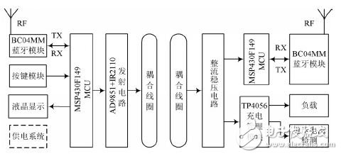
Figure 1 Bluetooth wireless charging system design block diagram
2.2 Bluetooth transmitting and receiving module
The BC04MM Bluetooth module supports UART, USB, SPI and other interfaces, and supports SPP Bluetooth serial port protocol, which can be easily connected to the Bluetooth device of the PC, and can also realize data intercommunication between the two modules. And because of its small size and low power consumption, it can be integrated into other devices or carried around.
2.3 Magnetically coupled resonant module
Magnetically coupled resonance technology is an electromagnetic resonance system that uses electromagnetic fields as a medium and utilizes two or more high-quality factors with the same resonant frequency. This module is the key to the wireless charging system and can be divided into transmitting circuits and receiving circuits. The transmitting circuit is composed of a driving circuit and a power amplifying circuit. The AD9851 is controlled by a single-chip microcomputer to generate a PWM signal, and the IR2110 is controlled to operate, and a square wave of 100 kHz is generated as an excitation signal to drive the resonant power amplifier circuit.
The resonant power amplifier circuit is composed of an IRF540 switch tube and an LC parallel resonant circuit. The oscillating coil is a coil with a diameter of 3.8 cm and an inductance value of 30 μH. The transmitting circuit is shown in Fig. 2.
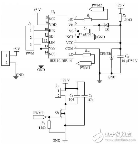
Figure 2 drive circuit and power amplifier circuit
The receiving circuit in the magnetic coupling resonance module is composed of an LC series circuit, a rectifying circuit and a voltage stabilizing circuit. The receiving coil type in the LC series circuit is the same as that of the transmitting coil. When the excitation signal frequency is close to the natural frequency set by the coil, resonance occurs, and energy can be transmitted from the transmitting end to the receiving end. The rectifier circuit uses the Schottky tube SS34 to form a full-wave rectifier circuit, which converts the AC signal into a DC signal. The voltage regulator circuit is composed of LM2596 and its peripheral circuits. After full-wave rectification, the output voltage is too high and unstable with load. Therefore, it needs to be stepped down by the LM2596 to achieve a constant voltage output of 8 V, which provides a stable power supply for the rear stage circuit. .
2.4 Charging Management Module
The module uses the charge management chip TP4056, which is a complete single-cell lithium-ion battery with a constant current / constant voltage linear charger with charging prompt and automatic stop charging. Connect the enable end of the chip to the P5.3 pin on the MCU, and control the chip operation by the MCU. Connect a 1.5 kΩ resistor to the PROG pin to set the output current of the BAT pin. Through actual circuit testing, the BAT pin can achieve a 4.2 V/500 mA output.
2.5 single chip control circuit
The MCU control circuit mainly realizes the following functions:
(1) Send data and control commands through the MCU UART interface to control the Bluetooth module to achieve matching between the Bluetooth modules; to generate PWM waves by transmitting part of the single-chip microcomputer to control the AD9851; to control the TP4056 enable terminal by receiving the P5.3 port of some single-chip microcomputers; The internal ADC12 module of the wireless receiving part of the microcontroller collects the charging current and voltage.
(2) The control and display circuits are configured in P1, P2, and P5 ports. The wireless transmitting part of the MCU mainly completes the corresponding operations of reading the keys. The control system realizes the functions of pairing, connecting, disconnecting and Bluetooth off, and displays in real time through the LCD1602.
3 software design
The software part of the system mainly includes wireless transmission part software design and wireless receiving part software design.
The wireless transmission part software design is mainly completed: system initialization, detecting buttons, controlling the Bluetooth module to send and receive data, controlling the AD9851 work, etc., as shown in Figure 3.
The wireless receiving part of the software design is mainly completed: system initialization, control Bluetooth to send and receive data, real-time detection of voltage and current data, control TP4056 work and LCD1602 display, as shown in Figure 4.
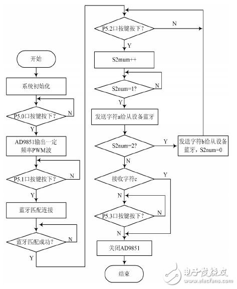
Figure 3 Wireless transmission part flow chart
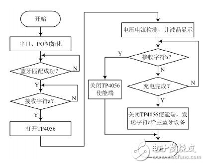
Figure 4 Wireless receiving part flow chart
Study on Transmission Characteristics of Magnetically Coupled Resonant Wireless Charging System
For a magnetically coupled resonant wireless energy transfer circuit, the transmission power and efficiency are affected by the following parameters: drive source voltage, transmission distance, and parameters such as coil diameter, number of turns, and wire diameter. The following is a test of the completed circuit to study the relationship between transmission efficiency and these influencing factors.
4.1 Relationship between drive signal frequency and transmission efficiency
In this study, the coil distance was 6 mm, the inductance of the two coils was 16 μH, the diameter was 55 mm, and the natural frequency of the coil was 126 kHz. The test process increases the drive frequency from 80 kHz in units of 5 kHz, and the transmission efficiency is calculated from the measured data, resulting in a relationship curve as shown in FIG. It can be seen from the relationship curve that when the driving signal frequency is 125 kHz, the transmission efficiency is the highest, which is close to the natural frequency of the coil. The above data proves the relationship between the resonant frequency of the magnetically coupled resonant wireless charging circuit and the natural frequency, that is, the circuit has the strongest energy transmission capability when the two are approximately equal.
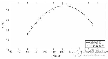
Figure 5 Drive signal frequency and transmission efficiency curve
4.2 Relationship between two coil distance and transmission efficiency
During the test, the distance between the two coils was changed, the other parameters were kept unchanged, and the data was calculated and transmitted, and the relationship curve shown in Fig. 6 was obtained. When the distance D is close, the transmission efficiency is high. When D≤11 mm, the efficiency is greater than 50%. As the distance increases, the transmission efficiency decreases, which is consistent with the theory.
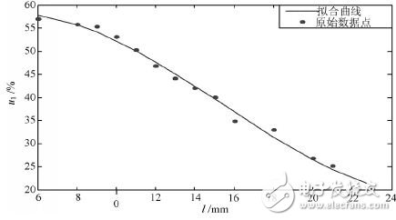
Figure 6 Relationship between two coil distances and transmission efficiency
4.3 The natural frequency of the receiving end is constant, the inductance value changes (the transmitting end does not change) and the transmission efficiency
Change the inductance value and capacitance value of the receiving end, but the natural frequency remains unchanged at 125 kHz, and other parameters remain unchanged. The output voltage and current are measured, and the transmission efficiency is calculated, and the relationship curve shown in Fig. 7 is obtained. There is also a set of data after the ferrite is added to the center of the coil.
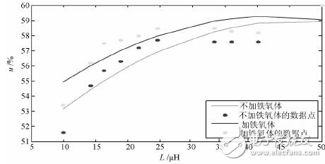
Figure 7 Relationship between inductance value change and transmission efficiency
It can be seen from the relationship curve that as the inductance value increases, the transmission efficiency increases. Therefore, increasing the inductance value is also a method of increasing the efficiency, but the inductance value cannot be increased without limit, and the input power is increased to a certain extent. Will not be able to drive the load. After the ferrite is added to the coil, the efficiency is increased, but it is not obvious. In practical use, it is possible to select whether or not to add a magnetic substance according to actual requirements.
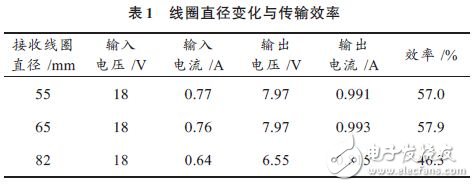
4.4 The inductance of the receiving end is constant, the relationship between the diameter change of the coil and the transmission efficiency
The coil diameter is an important factor affecting the inductance parameters. The coil diameter is changed during the test, but the natural frequency is kept unchanged. The test results are shown in Table 1. From the data, it can be seen that the diameter is increased and the transmission efficiency is improved, but the coil is If the diameter is too large, the magnetic lines will cancel each other and the efficiency will decrease.
5 Conclusion
The function of the Bluetooth wireless charging system designed by the MSP430F149 MCU and the magnetically coupled resonant module is verified. When D=6 mm, the transmission efficiency is 57%, and the lithium battery of 1 200 mA·h can be charged. And the design has the following characteristics:
(1) Replacing the traditional charging line with electromagnetic resonance technology to transmit electric energy, making charging more convenient and quick;
(2) Using Bluetooth technology to achieve one-to-many or many-to-many matching connections;
(3) It has the function of charging status, charging control and automatic power-off after the battery is full.
SIMATIC S7-200, S7-300, S7-400, S7-1200, S7-1500, SIMATIC ET-200 Distributed I/O, SIMATIC WinAC, Siemens Process Control PCS7, Siemens SCADA WinCC, Operator Panels, Touch Panels, Industrial Networks: Profibus, Profinet and Modbus.
Control Concepts owns the software for all of these platforms so we are ready to go on service calls to troubleshoot your existing controls or program for new applications. We can assist you in migrating from older platforms such as S5 to S7.
Simatic C1 Modules
Simatic C1 Modules,Initializing Pulse Encoder,HMI Larger Smalcomparators
Xiamen The Anaswers Trade Co,.LTD , https://www.answersplc.com