The fingerprint identification process is similar to the process of all biometric feature recognition, and is divided into two parts: user registration and feature matching. First, a fingerprint image needs to be recorded, and the acquired original image is processed, including image enhancement, segmentation, refinement, binarization, and the like. Then, the detailed features of the fingerprint are extracted. The common feature points have bifurcation points and endpoints. Finally, the generated templates are stored in the system database. Regardless of the process of verification or identification, the fingerprint image of the user to be identified needs to perform the same image segmentation, refinement, binarization, feature extraction and other steps to generate the same data format as the database template. , the comparison is made, and the result of the recognition is obtained.
The precondition for the existing fingerprint recognition algorithm is to use the same fingerprint reader to collect fingerprints or authentication. Therefore, many users on the Internet can only use the same type of fingerprint reader to achieve authentication. Practice has proved that if you change to a different fingerprint reader, the performance of the verification system will be greatly reduced. This is because the fingerprint reader has no standard interchange. Provisions.
Due to the different algorithms used by the various recognizers, each system that uses the fingerprint recognizer requires an individual login, and the authentication must use the same type of identifier as that used when logging in. This means that individuals and systems need to keep multiple different kinds of recognizers. The general algorithm for solving the problems of different recognizers has become a very interesting topic in the current research, so that users can use different recognizers on their own computers, which is convenient for the use of online fingerprint verification systems.
Since some types of fingerprint sensors are only suitable for the same type of collector verification, in order to allow more users to use and prevent counterfeit users from trying to deceive the system, multi-sensor fingerprint fusion is necessary to improve the performance of the system. This paper proposes a simple fusion strategy to study two types of commonly used fingerprint sensors, an optical sensor and a capacitive sensor. After acquiring two images, the two types of sensors respectively extract the minutiae points through the pre-processing program and match the template fingerprints respectively to obtain two matching scores. Then, the two matching scores are obtained through the fusion rule to obtain the final matching score, and the single matching score is obtained. The comparison of sensor performance shows that the results of the fusion have greatly improved the performance of the system.
1 proposed fusion framework
Figure 1 is a block diagram of the proposed multi-sensor fingerprint verification system. First, the user's fingerprint image is captured by optical and capacitive sensors. Then, the image is pre-processed and the features of the fingerprint images acquired by the two types of sensors are extracted separately. The minutiae-based matching algorithm is applied to the optical and capacitive minutiae points respectively. Therefore, there are 2 matching scores and fusion using fusion rules. These scores.
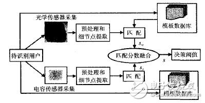
Figure 1 Multi-fingerprint sensor verification system framework
1.1 Types and working principle of fingerprint sensors
Due to the many specifications of today's fingerprint sensors, there is still no proper and uniform protocol and standard. At present, the existing sensors on the market mainly include optical sensors and capacitive sensors.
1.1.1 Optical sensor working principle
Its basic principle is as follows: the finger is pressed on one side of the glass plane, and the LED light source and the CCD camera are mounted on the other side of the glass. The light beam emitted by the LED is irradiated to the glass at a certain angle, and the camera is used to receive the reflection from the glass surface. Back light. The ridge line on the finger is in contact with the surface of the glass, and the valley line is not in contact with the surface of the glass. Therefore, the light that illuminates the surface of the glass in contact with the portion of the fingerprint ridge is diffusely reflected, and the light that illuminates the surface of the glass corresponding to the valley line of the fingerprint is irradiated. It is totally reflected, so that in the image captured by the CCD camera, the portion corresponding to the fingerprint ridge line is darker, and the portion corresponding to the fingerprint valley line is lighter.
1.1.2 Working principle of capacitive sensor
The principle of the capacitive sensor produces different capacitances between the finger skin and the chip according to the ridges and valleys of the finger pressed onto the acquisition head. The chip obtains a complete fingerprint by measuring different electromagnetic fields in the space. From this construction principle, the anti-counterfeiting of the fingerprint can be greatly improved. Forged fingerprints are generally made of insulating materials such as silicone or white gelatin, which cannot be imaged on capacitive sensors, thus making counterfeit fingerprints useless. However, capacitor technology chips are expensive and susceptible to interference.
1.2 Fingerprint image processing
In the identification process, firstly, the fingerprint J is collected by the fingerprint collection instrument. Because the image quality is not high when the fingerprint image is collected or the fingerprint distortion occurs due to uneven force in the process of capturing the fingerprint, the fingerprint image segmentation is often inaccurate. It brings more difficulties to subsequent fingerprint recognition, resulting in rejection or misunderstanding of the fingerprint automatic identification system. Therefore, the first key technology after fingerprint collection is to preprocess the collected fingerprint image, including the fingerprint. Image enhancement, binarization and refinement. After the pre-processing is completed, feature extraction can be performed, and then feature matching is performed, and the matching result is output, as shown in FIG. 2 .
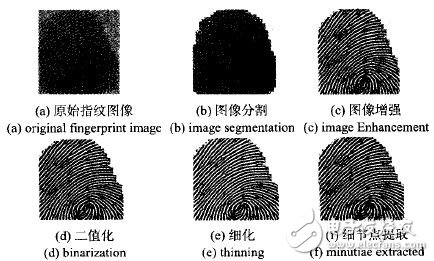
Figure 2 Fingerprint image preprocessing steps
Finally, the minutiae points are extracted. The minutiae points are defined as: endpoints and points (see Figure 3). The end points of the lines are the end points of a stripe road, and the line bifurcation points are separated by a stripe road into two stripe roads. point. These two feature points have the greatest probability of appearing in the fingerprint image, are most stable, easy to detect, and are sufficient to describe the uniqueness of the fingerprint.
Figure 3 fingerprint detail point type
The matching of the two fingerprint images mainly solves the problems of rotation, translation and deformation. In this paper, the fingerprint matching input is the point set corpse and Q of two feature points, one of which is extracted from the input fingerprint image, and the other point set Q is extracted from the standard fingerprint image in advance. Come out and store it in the template library. These two sets of points are represented as
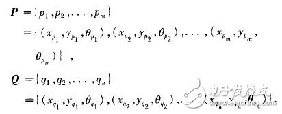
among them, Record 3 pieces of information of the i-th feature point in point set P: coordinates, Y-coordinates and directions,
Then, three pieces of information of the jth feature point in the point set Q are recorded: x coordinate, y coordinate and direction. Assuming that the two fingerprints can be completely matched, the fingerprint image in the template can be obtained by some transformation (rotation, translation and expansion) of the input fingerprint. Therefore, the point set P can be transformed by rotation, translation and expansion. Approximate to point set Q.
In order to be able to convert a certain feature point in the input fingerprint image into a corresponding position in the template fingerprint image according to a certain transformation manner, it is necessary to know the corresponding transformation factor, and Δx and Δy are respectively the translation factors in the x, y direction. , Δθ is the rotation factor. The determination of the matching reference point is obtained by judging the similarity degree of the two triangles. After the matching reference point and the transformation factor between the two fingerprint images are obtained, the identification fingerprint is rotated and translated relative to the template fingerprint. In order to determine whether the two fingerprints are from the same finger. In this paper, the coordinate position of the feature point of the transformed fingerprint to be identified and the direction of the ridge of the area are obtained. Then, the transformed set of fingerprint feature points to be identified is superimposed on the template fingerprint feature point set, and the number of coincident feature points in the two feature point sets is detected. Since the matching in this paper is a kind of inexact matching, even if it is a pair of matching feature point pairs, their questions will not completely coincide. There is always a certain deviation in position and direction, so there must be certain Deviation tolerance.
To this end, a method called defining a box is employed herein. For each feature point in the template fingerprint feature point set, a rectangular area around it is selected as its bounding box, as long as the feature points in the transformed fingerprint to be identified are superimposed and fall within the area, and the direction is basically Consistently, it can be considered that the two feature point pairs are a pair of matched feature points.
Finally, the algorithm counts the number of all matching feature points and converts them into matching scores by the formula (1). Among them, maxscore is the maximum matching score obtained by superimposing the matching number of minutiae points. Temp_Num and Input_Num are templates respectively. And the number of minutiae points for entering fingerprints
The calculated matching score represents the degree of similarity between the two fingerprints compared. The larger the parameter value, the higher the degree of similarity, and if the score is small, the user is not necessarily the user he claims, and the access will be denied.
The algorithm used in this paper is a typical point pattern matching algorithm based on feature point coordinate model. It makes a deeper study on the determination of the most difficult step-by-reference point and the calculation of the transformation parameters in the matching process. The reference point is determined according to the relationship between the feature points of the three neighbors, and the transformation parameters are obtained. The algorithm can speed up the determination of the reference point to a certain extent, thereby improving the speed of the entire matching algorithm. At the same time, the algorithm determines the transformation parameters according to multiple points, instead of the usual point of view, to some extent, it can eliminate the deviation of the position and angle introduced in the feature extraction process, and obtain more accurate transformation parameters.
1.3 Fusion of optical and capacitive sensors
So, Sc is the matching score obtained by the image acquisition matching algorithm collected by the optical sensor and the capacitive sensor, respectively, and the s-synthesized score and S. So, Sc has the following relationship
Compare S with the set threshold: if:S > threshold system allows entry, true; otherwise, the system rejects the user, of course, the above method can also be used for more than 2,.
According to equation (2), two types of matching score conversion execution fusion rules are studied. The first type of fusion rules belong to the so-called fixed fusion rules because they do not require parameter estimation, especially the median matching scores of the two types of sensors.
The second type of fusion is the so-called training sample rule because they require the sample to be trained multiple times in order to obtain the desired threshold score, and the sample is trained using equation (4).
In the formula, W0, W1, and W2 are weight vector. Obviously, the effect of median fusion is worse than logical fusion. The process of logical fusion is based on the median value. After multiple iterations, a set of appropriate weights can always be found. The vector (W0, W1, W2) is such that the threshold score S is close to the optimal value.
2 Experimental results
Randomly selected 20 people, each using 3 fingers, respectively, thumb, index finger, middle finger, using optical and capacitive sensors, each finger pressed 10 times, each person collected the number of fingerprints is 6 & TImes; 10 = 60, the total fingerprint 20&TImes; 60=1200. The matching score for each of the two sets of validation algorithms. The first match is called the "true match score (between real users) G set, and the second is the "false match score" ("fake user question") I set.
The above set of random subdivisions are two sets of the same size: G=G1 U G2, I=I1 U I2, G1, G2 and I1, I2 are separate sets of G and I, respectively. The training set Tr={G1, I1} is used to calculate the weight of the logical fusion rule, and the test set Tx={G2, I2} is used to evaluate and compare the performance of the algorithm. It contains the following indicators:
The equal error rate (EER) of the training sample set, that is, the percentage (FRR) when the true user is rejected by the system error is equal to the percentage (FAR) of the fake user being accepted by the system error.
Table 1 summarizes the results of calculating the EER of the training sample and the FAR and FRR of the test sample.
Table 1 Indicator EER for single sensor and multi-sensor fusion calculation results. FAR, FRR
As can be seen from Table 1, the performance of the capacitive sensor is significantly worse than that of the optical sensor. The main reason is that the contact area of ​​the capacitive sensor when capturing images is much smaller than that of the optical sensor. The number of minutiae points directly extracted from the images it collects is small, so the extracted minutiae points cannot be correctly matched to each other.
From the fusion results of the equal error rate calculations, the performance is also greatly improved, and the logical fusion reduces the EER from 3.6% to 2.9%. The results of the test samples also show that the fusion improves the robustness of the system. In fact, after the logical fusion (line 5 of Table 1), the performance of the training samples (column 2 of Table 1) and the performance deviation of the test samples (Table 1) Columns 3 and 4) have been greatly reduced.
The experimental results are compared with the Gian Luca experimental results, and the results are lower than those in the literature [7]. The reason may be that the performance of the collector used in this paper is relatively poor, so that the quality of the obtained fingerprint image is not ideal and the index is weak. In addition, it may be that the matching results obtained by the algorithm used in this paper are not ideal.
3 Conclusion
This paper presents a multi-sensor fingerprint verification system based on optical and capacitive sensors. The experimental results show that the performance of the verified multi-sensor system is better than that of the best single sensor (optical sensor), and the complementarity between the optical and capacitive sensor matchers also indicates the possibility of multi-sensor fusion. In theory, the system itself also gets a very low verification error rate. The feature extraction process is applied to the images collected by each collection device, and a simple fusion rule is applied to improve the verification performance of the system. Therefore, it is simple and easy to integrate different types of sensors to improve system performance.
WOSENS TECHNOLOGY Co., LTD , https://www.wosenstechnology.com