Huang Yongming, Chen Jimin, North China Institute of Computing Technology
Keywords: VPX bus; modular; high reliability
With the rapid development of computer bus technology and chip processing capabilities, the volume of computing platforms has been continuously reduced, and system performance has been increasingly enhanced. As the application of the computing platform in the on-board computer system, due to the characteristics of the vehicle environment, while the on-board computing platform is continuously developing toward miniaturization, high mobility, and multiple redundancy, the ability to resist harsh environments has become increasingly important.
With the change of the architecture of the computing platform, the construction method of the on-board computing platform has undergone the following stages of development: First, based on the traditional computer architecture, the method of interconnection between equipment, this method is relatively simple to build the platform, the disadvantage is Can not meet the requirements of sturdiness, but also can not meet the requirements of miniaturization, modularization and hot-plugging; followed by a method of building a system using a parallel bus such as CompactPCI or VME, this method by changing the architecture of the on-board computing platform, The requirements of the application were satisfied within a certain period of time, but along with the steady increase of the data transmission rate, the parallel bus, which has been quite perfect in technology, gradually reached the limit. To achieve a higher I/O transfer rate, a better way is to convert parallel data transmission into a serial switch structure. Therefore, a method based on the CPCI-Express, VXS, and VPX serial bus construction systems has emerged. This is also a vehicle-mounted calculation. The development direction of the platform.
The most fundamental idea of ​​CPCI-Express is that it can be compatible with the PCI-Express bus using the Eurocard specification. It is a point-to-point serial interconnect bus technology with a transfer rate of 2.5 Gb/s or more. VXS is a switched serial extension standard developed by VITA (VMEbus international trade association). It adds structural technology to the traditional VME bus. Based on the preservation of some pin connectors, it also uses MuhiGig RT2 from Tyco. High-speed connectors, the new connector can increase the data bus transmission bandwidth to 5 Gb / s, and provide more custom differential pair signal, which facilitates system expansion and upgrade. VPX is also a set of bus standards developed by VITA to enhance the circuit board and connector formats. It supports many high-speed signal standards including PCI-Express, Serial RapidIO, and Gigabit Ethemet. It conforms to IEEE 1 101 3U and 6U standards and supports hot-swapping. , with 10 Gb/s interface bandwidth. All VPXs use the same type of RT2 connector as VXS, which provides developers with more custom signals, improves design flexibility, and is highly scalable. The VPX bus combines the many advantages of CPCI-Express and VXS, greatly improving the performance and scalability of the bus. As a new generation of bus products for military reinforcement systems, the VPX bus is widely used in harsh military environments.
Based on the status quo of vehicle-mounted computer systems, combined with development needs, and with reference to domestic and international experience, the authors designed a high-reliability vehicle-mounted computing platform based on VPX bus using advanced technologies, providing a solution and solution for the development of vehicle-mounted computing platforms.
1 Overall design
The computing platform adopts a modular design, and each module follows a unified interface standard. The module completes the power supply and information exchange through the backplane interconnection. The backplane completes the communication of each slot through the VPX-supported Gigabit Ethernet. To improve reliability, the system adopts a redundant dual-network bus architecture. To enhance security, the system's data processing and transmission are designed to be both internal and external networks. The internal and external networks are isolated and only connected through a firewall. The system can be divided into three parts from the perspective of logic function: internal network part, firewall, external network part. System logic diagram shown in Figure 1.
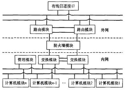
Figure 1 overall system logic diagram
2 Introduction to each module
2.1 Switch Modules and Routing Modules
The switching module is the core module of the internal communication of the platform. All modules of the internal network complete the communication through the switching module. In addition to the basic 3 layer switching function, the switching module also supports VRRP (virtual router redundant protocol), and provides an external device interconnection interface and a cascaded interface between the platforms.
The development of switching equipment has undergone the design of a general-purpose CPU and a dedicated ASIC. The most popular design method at present is the use of a network processor (NP). The general CPU has high overhead in extracting, comparing, and aligning bit fields in the data packet header. Due to the interrupt handling of the general CPU and the Cache hierarchical structure, the real-time processing of the network communication needs to store the data packet in the buffer multiple times. The cost is also relatively large. The dedicated ASIC chip is mainly designed for a special protocol. Its execution efficiency is high, but the ASIC also has problems of poor scalability and low flexibility. The network processor has obvious advantages compared to the two: it has strong programmability, better flexibility, high-speed parallel processing, and better openness and scalability. Based on the advantages of a network processor, the switching module is implemented using a network processor.
To achieve high reliability of the platform, the backplane's internal network and external network are designed as dual networks. There are two switch modules in the internal network, namely, a master switch module and a backup switch module. These two switch modules are connected to each other. To two internal networks. When the platform works normally, only the master switch module bears the forwarding task, and the backup switch module is in the ready listening state. The master switch module periodically sends VRRP packets to announce its configuration information (priority, etc.) and working status. The Backup switch module determines whether the master switch module works normally by receiving VRRP packets. When the backup switch module finds that the master switch module is broken, the backup switch module switches to the master switch module to maintain network communication. After calculation, the switching time between the two switching modules is less than 3 seconds.
The routing module has routing and switching functions, and provides wired access means to ensure communication under various communication protection conditions and terrain conditions. It provides external device interconnection interfaces and cascaded interfaces between platforms. The routing module supports VRRP as well as the switching module. There are two routing modules in one platform, which is functionally equivalent to a virtual router, which improves the reliability of the platform.
2.2 Computer Module
The computer module can work independently or with an external expansion server to complete data processing and system control. The computer module consists of a computer control module and an operation terminal. The computer control module is responsible for information processing, integrated processor, chipset, with network, display and I/O interfaces, and can support the clustering of multiple computer control modules. The operation terminal integrates a mouse, a keyboard, and a display, and is an operation providing device. The operation terminal and the computer control module are wired through the interface.
2.3 Management Module
The design of the management module adopts the intelligent platform management interface (IPMI) technology. A dedicated management bus is designed on the backplane to implement monitoring and management of all modules, and to ensure the normal operation of equipment and timely prompts for faults. IPMI is an open standard hardware management interface specification. It is located between the system's hardware platform and system management software. It does not rely on operating systems and management application software to provide hardware management interfaces for system management. The IPMI-based intelligent platform management system has the functions of monitoring, recording, and alerting the platform independently of the CPU, BIOS, and operating system. The monitored hardware information includes CPU operation, fan speed, system temperature, and power supply voltage. When the IPMI controller senses an abnormal situation, it records the status and events of the entire system operation in the form of Et records, and the warning informs the relevant personnel to handle the problem.
2.4 Summary
The above four kinds of modules are the core modules of the platform and are the necessary modules for building platforms. In addition, firewall modules and wired communication modules can be added as needed. The firewall module is located between the internal network switching part and the external network routing part. It is the only module that provides internal and external network interfaces in the platform. It has the function of protecting the internal network from intrusion by illegal users and preventing the leakage of intranet information. It can improve internal functions. Web security. The wired communication module supports point-to-point long-distance transmission of voice and data signals using optical fibers or covered wires in different environments.
All modules are hot-swappable and can be dynamically configured and managed. In the design process, thermal design, shock resistance, vibration, high and low temperature, electromagnetic compatibility, and three-anticipation design are all considered. The intranet module also only has an intranet interface. Similarly, the extranet module only has an extranet interface. Only the firewall module has intranet and extranet interfaces. Each module has the ability to independently power on, off, and reset. In addition to the switch slots and routing slots, each module can be swapped and swapped at other slots, providing high flexibility.
3 Backplane interconnection design
The backplane is the connection basis of all functional boards and provides the interconnection of functional modules. The reliability of the backplane has an important impact on the platform. To ensure high reliability of the backplane, first select a suitable backplane switching method. At present, the most widely used switching structures are mesh, single-star and double-star structures. The three interconnection methods are shown in Figure 2. The advantage of the mesh structure is that each node can be fully interconnected. Failure of any processing node will not lead to the collapse of the platform. Other nodes can still communicate by bypassing the failed node. At the same time, this structure has good scalability. However, when there are more than five devices that need to be interconnected in the system, the number of traces on the backplane and the number of interface pins will increase geometrically, which is not conducive to system applications with many slots. The single-star interconnection structure is a structure in which each processing node is interconnected through the switching node. The advantage is that the structure is simple, a processing node fails, other nodes can still operate normally, and communicate through the switching node. However, when the switching node fails, the entire system will crash, so the reliability is relatively low. The double-star structure combines the advantages of the mesh structure and the single-star structure, that is, the number of traces is saved, and the redundancy and backup of the mesh structure are also played. Comparing the advantages and disadvantages of the three structures, the platform uses a double star structure as the backplane interconnect structure.
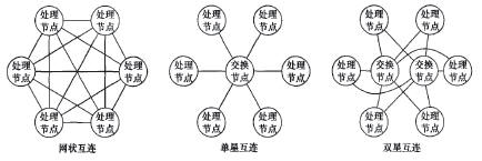
Figure 2 commonly used three kinds of interconnect structure
The backplane is designed with 16 slots and 5 buses. The backplane interconnect is shown in Figure 3. The slots 7 and 8 on the backplane are internal switch module positions; the slots 9 and 10 are the location of the external network routing module. In addition to the four slots fixed on the backplane, other modules can not be inserted, and other 12 slots can be freely inserted into other modules. The backplane has 5 busses—2 internal network buses, 2 external network buses, and 1 management bus. Both the internal network bus and the external network bus are dual-star designs. Bus pins of each module are distributed in P1 connectors. To P|6 connectors, all modules have P0 connectors for power supply and management.
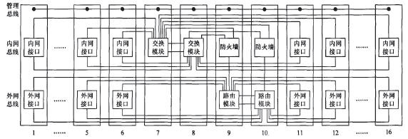
Figure 3 Backplane interconnection
4 power supply design
In order to enhance the reliability of the platform, the platform has a total of four power modules. Two power modules can work at the same time to satisfy the platform application. Three modules are open during normal operation, and the other is a hot backup. When a certain power module fails, the backup component automatically takes over its work and reports the power failure for replacement. Each power module provides two types of interfaces: AC input and DC input. The front end is connected to the in-vehicle power supply. Only one interface can be used at the same time. The DC input is 24 V. After conversion by the DC/DC module, 12V, 5V, 3V and other voltages are separated and sent to each module through the backplane. The AC input is converted to 24V (DC) after conversion by the AC/DC module. The same conversion provides various voltage outputs for the system. Module power supply is shown in Figure 4.
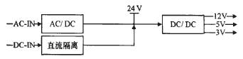
Figure 4 power supply design principle diagram
5 Concluding remarks
The above-mentioned computing platform adopts advanced VPX bus technology, which is characterized by high reliability, high performance, modularity, miniaturization, flexibility, and good environmental adaptability. It adapts to the development trend of on-board computer systems, and is easy for future systems. Extensions. Through adaptability, the platform can become an airborne and shipboard computing platform.
Insulation Board works well as a flame barrier insulation in appliances and electronics, and provides long-term performance at temperatures exceeding 482°F (250°C).
Transformer Insulation meets the high performance insulation requirements for new high-temperature, liquid-filled distribution transformer designs. This innovative insulation offers excellent thermal stability, low moisture absorption, high thermal conductivity and long-term reliability. This low-density board insulation is available in a range of thicknesses.
The products are applied to various power distribution systems and their components such as transformers, switch cabinets, motors, etc. The company abides by the credibility of the first, quality first, continue to work hard on the development and research of insulating materials products, consolidate the market leading position, and bow to provide the best service to users.
Insulation Board
Insulation Board,Insulation Beech Sheet,Phenolic Paper Laminate,Insulation Laminated Sheet
Yingkou Dongyuan Electrical Insulation Board Co.,Ltd , https://www.dy-insulation.com