I. Overview
Today's blood glucose meters and other home medical devices are small, portable, and easy to use. A good medical device logo is a result that patients can use every day and return accurate results. In the past few years, the trend of blood glucose meters has been to maximize patient comfort and convenience by reducing the amount of blood samples needed. At present, the blood collection samples of the equipment are very small, and blood can be collected from different parts. There is no need to collect blood from your fingers, which greatly reduces the pain of daily testing. The accuracy of the test results is improved by using better blood glucose test strips, electronics and advanced measurement algorithms. Other conveniences include quick results, edge-filled test strips, and test strip illumination.
1, blood glucose meter type
There are now two instruments in the market for continuous and discrete (single) testing, and implantable and non-invasive instruments are advancing. Continuous testing of blood glucose meters can only be used on prescription, using a subcutaneous electrochemical sensor to set the test interval. A single test blood glucose meter uses an electrochemical or optical reflectance method to measure blood glucose levels in mg/dL or mmol/L. Most blood glucose meters are electrochemical instruments. Electrochemical test papers have electrodes that provide precise biasing in a digital-to-analog converter (DAC) and measure the current proportional to blood glucose using the electrochemical reaction of the test strip. There may be one or more channels, usually a transimpedance amplifier (TIA) that converts the current into a voltage and then uses an analog-to-digital converter (ADC) for measurements. The full-scale current measurement of the test strip is 10μA to 50μA with a resolution of less than 10nA. Since the test strip is temperature sensitive, it is necessary to measure the ambient temperature.
Optical reflective test strips use color to determine the blood glucose concentration of the blood. The calibrated current typically flows through two light emitting diodes (LEDs) that alternately illuminate the color test strips. A photodiode monitors the intensity of the reflected light, determined by the color of the test strip, and the color of the test strip depends on the blood sugar level of the blood. The photodiode current is converted to voltage by TIA to make measurements with the ADC. The photodiode has a full-scale current range of 1μA to 5μA with a resolution of less than 5nA. This method requires measuring the ambient temperature.
2, test paper calibration
Test strips usually need to be calibrated according to the meter to accommodate the manufacturing variations of the strip. Calibrate by manually entering the code or inserting a pack of test strips into the reservoir. EPROM or EEPROM memory transfers more information and has significant advantages over manual input coding. 1-Wire® memory is ideal for this type of application because the unique identification code for each 1-Wire device ensures the correct test strip is used.
Some oximetry test strips do not require user coding. There are three ways to accomplish this “self-calibrationâ€: strict production control, built-in calibration for each test strip, or calibration on the test strip of the loaded instrument. A set of test strips inside the meter also helps with testing, without the need for user handling and insertion for continuous testing.
Second, the system design
Modern blood glucose meters are increasingly using touch screens to provide a friendly graphical user interface (GUI) that makes the programming process more intuitive. The visual, audible, and tactile responses to user input help designers improve the user experience. Maxim's advanced touchscreen controllers provide haptic feedback, touch processing to reduce bus throughput, and autonomous mode for precise gesture recognition.
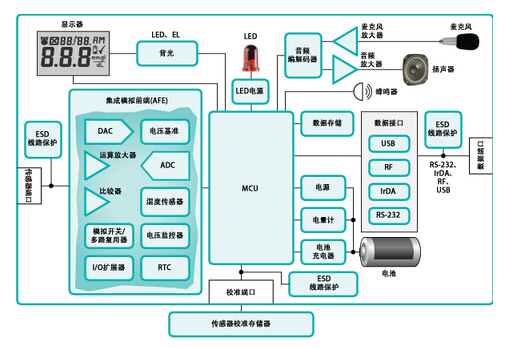
Blood glucose meter system block diagram
1, accuracy and precision
Optical reflectometry and electrochemical blood glucose meters require analysis of currents in the range of a few nanoamps. If the meter requires calibration during production, the device must have extremely low leakage current and supply voltage, temperature, and time drift in order to meet the meter's error specifications. The main technical specification of the operational amplifier is to have a very low input bias current ("1nA"), high linearity and stability when connecting capacitive electrochemical test strips. For both types of blood glucose meters, op amps are typically configured as TIAs. The main technical specifications of the voltage reference include: temperature coefficient below 50ppm/°C, low time drift and good linearity, load regulation. A 10-bit or 12-bit DAC is used to set the bias voltage of the electrochemical test strip and set the LED current of the light reflective test strip. Sometimes, electrochemical test strips use a comparator to detect when blood is added to the test strip. To save power during waiting for blood collection, to ensure that the reaction area is filled with blood. Different types of blood glucose meters have different ADC requirements, but most require a resolution of no less than 14 bits and require low noise to achieve repeatable test results. Some applications add a programmable gain stage in front of the ADC to extend the dynamic range, in which case 12-bit resolution is available.
2, temperature measurement
Ideally, the temperature of the blood on the test strip should be measured, but the ambient temperature around the test strip is usually measured. Temperature measurement accuracy varies with indication type and chemical composition, typically between ±1°C and ±2°C. Temperature measurements are made using a separate temperature sensor IC or remote thermistor or an ADC with a PN junction. A half-bridge configuration thermistor with the same reference drive as the ADC will provide more accurate results because this design eliminates all voltage reference errors. Remote or built-in PN junctions can be measured with the Precision Integrated Analog Front End (AFE).
3, electrochemical test paper configuration
Most test strips are special accessories and the test strips of different glucose meter manufacturers vary. Differences include reagent formulation, number of motors, number of channels, and biasing of reagents. The simplest configuration is a self-biased test strip (Figure 1) with two electrodes that measure the current at the working electrode and the common electrode grounded.

Figure 1. Electrochemical test strip in self-biased configuration
Multiple channels can be present on one test strip; additional channels are used for baseline measurements, initial blood tests, or to ensure that blood has filled the reaction area. Another configuration uses active driving of two electrodes and measuring at the common electrode. Another more advanced design is the counter configuration (Figure 2).
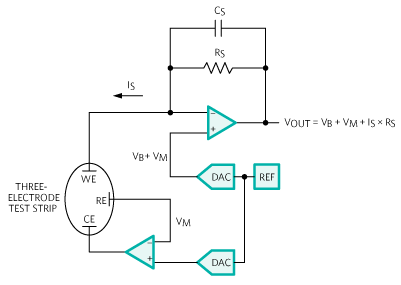
Figure 2. Electrochemical test strips with counter configuration
There are three electrodes here that measure the current at the working electrode, while a load-sensing circuit drives the common and reference electrodes. This configuration has an important advantage: the bias voltage of the reflective area on the test strip can be more accurately controlled and maintained during the measurement process. The disadvantage of this design is that it is more complicated and requires a higher margin to allow the negative swing of the load-sense amplifier to maintain the bias during current flow.
4. Integrated analog front end (AFE)
Maxim's high-precision AFE integrates all of the features mentioned above to meet the specifications and performance required by the blood glucose meter. AFE is also suitable for similar applications such as coagulation and cholesterol analyzers.
5, display and backlight
Most blood glucose meters use a simple 100-segment liquid crystal display (LCD) that can be driven by an LED driver integrated into the microprocessor. Some blood glucose meters have more complex dot matrix LCDs that typically require modules assembled using glass, bias, and drivers. The dot matrix display also requires additional memory to store the display content. There are also color displays that require more and higher voltages than segment or dot matrix LCDs. Backlighting can be added by using two white LEDs (WLEDs) or electroluminescent sources.
6, the data interface
The ability to load test results into a computer has been around for many years, but there are very few instruments that use data interfaces. Initially, in order to reduce instrument costs, the added cost of this feature was designed into proprietary cables. Instruments have now transitioned from proprietary data interfaces to industry standard interfaces such as USB and Bluetooth®. The increased cost of these open interfaces is transferred to the instrument, and the mobile drive components initiated by the ConTInua Health Alliance facilitate the transfer of patient data to the rehabilitation center.
7, audio
The audible indicator can be a simple buzzer or an advanced voice device that is convenient for visually impaired people. A simple buzzer can be controlled by one or two microprocessor ports with pulse width modulation (PWM). By adding an audio codec and speaker and microphone amplifiers, you can achieve more advanced voice indications, even test result audio recordings.
8, power and battery management
A blood glucose meter with a simple display can be powered directly from a button lithium battery or two AAA alkaline batteries. To maximize battery life, the device requires a button lithium battery to operate from 3.6V to 2.2V, and an AAA alkaline battery that operates at 1.8V. Switched boost converters can be used if the electronics require a higher or regulated supply. Turning off the switching regulator in sleep mode allows battery life to be extended directly from the battery, and the sleep circuit can operate at lower battery voltages. Adding backlighting or higher-level displays requires higher voltages and sometimes requires additional voltage. A more advanced power management solution is required at this time. A rechargeable battery, such as a lithium-ion (Li+) coin cell, can be used by adding a battery charger and a fuel gauge circuit. For the user, USB charging is a convenient option if the instrument provides USB. If the battery is detachable, safety certification may be required for safety and after-sales control.
9, electrostatic discharge
All blood glucose meters must meet the 61000-4-2 Electrostatic Discharge (ESD) requirements. Adding ESD line protectors with built-in ESD-protected electronics or on bare traces can help meet these requirements.
10, function expansion
If a sophisticated AFE is used to complete the core circuit design of the meter, and then additional functions need to be added, there is no need to redesign this part of the circuit. When using standard components with a single function designed for portable medical devices, the damage to the original circuit is minimized when new features are added. “Minimum damage†means lower risk, easy FDA-approved, faster time to market, and more functionality to meet patient needs. In order to protect personal health and control blood sugar at a normal level, people's demand for blood sugar testing is becoming more frequent.
Variable Rf Attenuator,Waveguide Fixed Attenuator,Fixed Attenuator In Microwave,Fixed And Variable Attenuator In Microwave
Chengdu Zysen Technology Co., Ltd. , https://www.zysenmw.com