In my previous blog post, I discussed the advantages of radio frequency (RF) sampling structures for broadband systems, but some systems require medium bandwidth or other important considerations. Active antenna arrays use multiple radiation mode antennas that are dedicated to producing more concentrated than a single component. This centralized mode increases the antenna gain to a predetermined target or user and provides interference suppression for areas outside the beam pattern at the same time, eliminating the need for excessive signal bandwidth.
A radar array is an active antenna system used to accurately locate a space target. The simple 3&TImes;3 array system shown in Figure 1 is capable of directing beams of two dimensions to track the target.
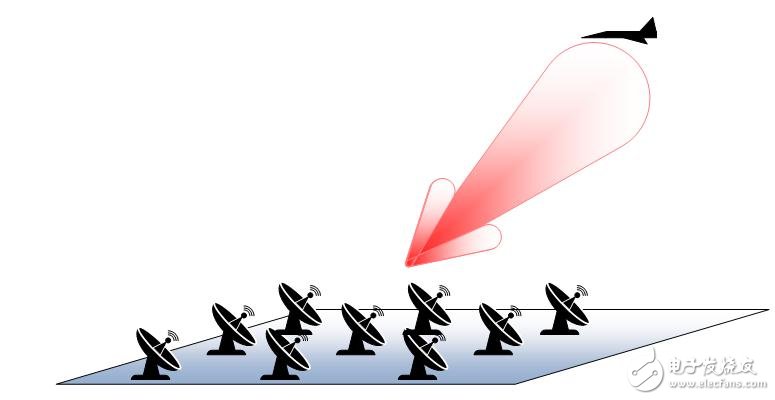
Figure 1: 3 & TImes; 3 radar antenna array
Each antenna element needs to have its own receiver. Smaller arrays may use eight components; very large arrays use thousands of components. These systems require a large number of receivers, so each receiver must be low cost and high power; and these systems require high dynamic range performance to distinguish targets in background noise and interference.
TI's 700-2700MHz dual channel receiver and 16-bit ADC and 100MHz IF bandwidth reference design (TIDA-00360) showcased the TSW16DX370 Evaluation Module (EVM), which is a superheterodyne receiver for active antenna array systems. machine. Figure 2 shows the block diagram. The reference design uses the TRF37B32 dual mixer to convert the input RF signal to an intermediate frequency (IF). The mixer has excellent gain, noise figure and input linearity for any high-end communication system. The power dissipation level of the TRF37B32 is the lowest in its class. This is very important in systems that must use tens to hundreds of receivers.
In normal operation, the device consumes approximately 1 watt per channel (frequency 1950 MHz). Current consumption depends on the frequency of the local oscillator (LO). If you need to further reduce power, the TRF37B32 offers a low power mode that reduces the nominal dissipation to 0.6 watts per channel (1950MHz). If you only need one channel, you can also choose to reduce the power of each branch separately, or reduce the power of the two channels for time division duplex (TDD) operation.
The TSW16DX370EVM includes an IF bandpass filter with a 1MHz bandwidth of 100MHz centered at 250MHz. The EVM uses an analog-to-digital converter (ADC) that provides 16-bit resolution and operates at 370 MSPS with the ADC16DX370. It has high signal-to-noise ratio performance for distinguishing small signals in background noise and serializes digital data using the JESD204B standard. The ADC16DX370 uses only two channels to transfer all data from two converters to a centralized processor. When dealing with multiple receivers, the TSW16DX370EVM has the advantage of compressing the digital interface to minimize routing.
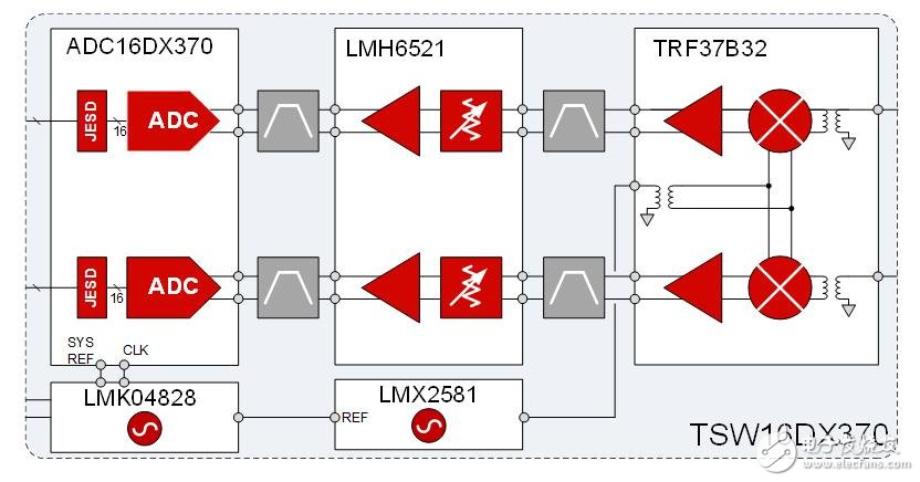
Figure 2: TSW16DX370 Receiver System Reference Design
Concentrated beams cannot guide the beam when needed, and their use is limited. The beam can be guided by changing the relative phase of each component using an online phase adjustment circuit. Figure 3 shows an analog phase adjuster circuit based on a varactor. Hybrid couplers keep the return loss of the input and output at a reasonable level. If the signal path includes this circuit, RF performance (especially intermodulation distortion) can be degraded due to the nonlinear performance of the varactor.
Another method is to place a phase adjuster circuit (shown in Figure 4) in the LO path such that the signal is a single frequency sinusoid rather than a modulated signal. This allows the desired phase adjustment to be achieved without affecting noise and linear performance as a function of regulating the voltage.
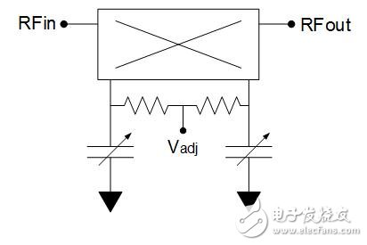
Figure 3: Phase adjustment circuit
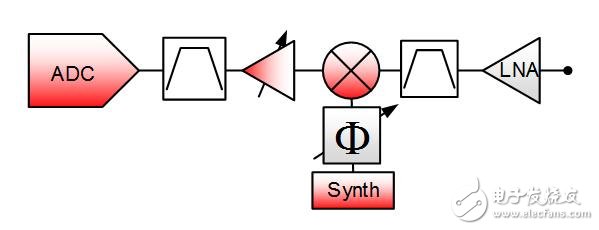
Figure 4: Phase-adjusted superheterodyne structure in the LO path
The receiver can maintain high performance with low power dissipation and can easily adapt to antenna arrays of any size.
Welcome to see the receiver solution that I will discuss next month to capture 1-GHz bandwidth signals.
Other resources
For more information on data converter design, please visit TI's Data Converter Learning Center.
Read the other articles in my RF sampling blog series.
Learn more about TI's RF sampling ADC.
ShenZhen Fahold Electronic Limited , https://www.fahold.com