In order to achieve the accuracy of the measurement data, choose the right instrument, the choice of test and measurement methods can not be underestimated.
The PA Power Analyzer power unit has two inputs: current and voltage. The measurement data obtained directly by FPGA and DSP is only the result of direct measurement of voltage and current ADC. Power, efficiency, harmonics, etc. are all based on voltage and current measurement. The result obtained by operation, such as power is the direct use of voltage and current. The calculation performed by the measurement result. Therefore, the accuracy of voltage and current measurement is very important. The resistivity of the conductor will affect the measurement results with temperature changes, device aging, line common mode/serch mode interference, measurement wiring method, and circuit wiring. Explain the measurement wiring method and circuit wiring.
1. Measuring wiring wiring
1) Irregular connection - the worst way to connect
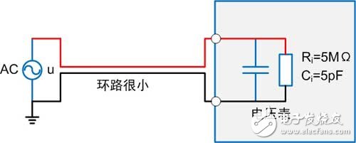
The two measurement lines in Figure 1 and Figure 2 are relatively scattered, forming a large loop. When a variable magnetic flux passes through the loop, according to the principle of electromagnetic induction, a noise voltage similar to the magnetic flux will be generated in the loop. The value measured by the instrument is not true.
![]()

Figure 1 Voltage irregular wiring

![]()
Figure 2 Current irregular wiring
2) General wiring method - parallel routing
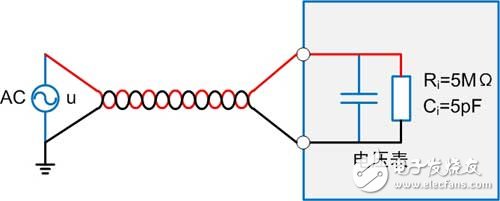
Compared with the scattered connection mode in FIG. 3 and FIG. 4, the loop formed by the measuring line is small, and is limited to between the connecting lines.
![]()
Figure 3 voltage parallel wiring wiring
![]()
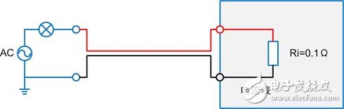
Figure 4 Current parallel wiring wiring
3) Better connection method - twisted pair
Figure 5 uses twisted pairs to connect the signal under test. Compared to parallel traces, the twisted pair breaks the loop into each twisted loop. The adjacent twisted loops produce opposite noise voltages to the external magnetic field. .
![]()
Figure 5 voltage twisted pair wiring
![]()
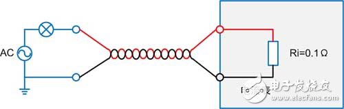
Figure 6 Current twisted pair wiring
4) Ideal wiring method - coaxial cable
The center of the outer conductor of the symmetric coaxial cable of Fig. 7 and Fig. 8 coincides with the inner conductor, and the equivalent area is 0, so that the magnetic field shielding effect is good.
![]()
Figure 7 voltage coaxial cable wiring
![]()

Figure 8 Current coaxial cable wiring
2. Circuit connection wiring
Power consumption impact
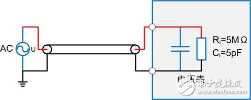
The use of load-matched wiring reduces the impact of power loss on measurement accuracy. The following is a consideration of the power supply and load resistance. Refer to the previous WeChat document "Characteristic Impedance of Power Measurement Instruments" for definition of ammeter loss
P=I2Ri voltmeter loss definition P=U2/RV, the square root of the voltmeter and ammeter internal resistance product is called the “power characteristic impedance†of the instrument.  When the load resistance RL > RP , the voltmeter loss is large, it is recommended to connect the ammeter, When the load resistance RL <RP , the current meter loss is large, it is recommended to connect the current meter to the external method.
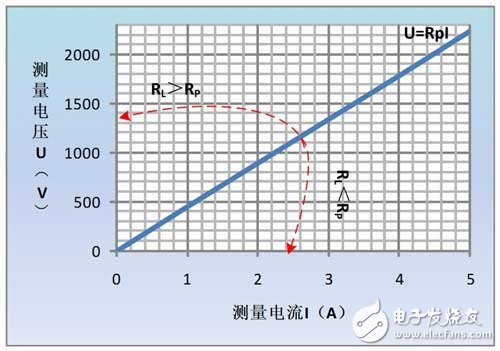
For example, PA5000, voltage input impedance Rv is about 2MΩ, current input impedance Ri is about 100mΩ, current range is 1A, voltage range is 300V, voltage and current consumption function is shown in Figure 9. At this time, Rp=200  When the load resistance RL is greater than 447.2 Ω, it is recommended that the ammeter be connected internally and reversed, as shown in Figure 10.
![]()

Figure 9 voltage current meter power loss function diagram
![]()
Figure 10 Internal and external decision criteria
Ip20 Ultra Thin Hca Power,Ultra Thin Power Supply,Light Box Power,Constant Voltage Light Box Power
Jiangmen Hua Chuang Electronic Co.,Ltd , https://www.jmhcpower.com