Here’s an amplifier designed specifically for indoor TV antennas. Despite its straightforward design, it performs exceptionally well.
The circuit for the indoor TV setup is illustrated in Figure 1. This circuit uses just one UHF transistor. The amplifier is powered by dual power supplies, G1 and G2. One of the key features of this circuit is that, for high-frequency AC signals, it functions as a common-emitter grounded circuit, while for the DC path, it acts as a common-base circuit. Consequently, this amplifier offers a high voltage gain while maintaining minimal noise levels. Since the power supply is split into two separate groups, the b-e and b-c junction currents of the transistor do not interfere with each other. As a result, the input and output of the circuit are well isolated, improving the operational frequency range and ensuring sufficient bandwidth. A single-stage amplifier can achieve a gain of up to 8 dB. For locations further away from TV stations, you can assemble a two-stage amplifier with a gain exceeding 15 dB. Due to the excellent isolation between stages, when setting up a two-stage amplifier, there won’t be any severe mismatches or self-excitations. The amplifier’s input and output feedlines both use 75Ω coaxial cables, making it compatible with TV antennas and TV ports.
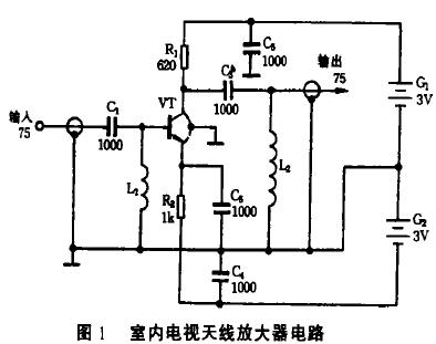
For component selection and assembly, the transistor VT should be a silicon NPN ultra-high frequency transistor such as the 3DG141, 3DG30C, 3DG30D, 3DG80, or 2G911. These transistors require fT ≥ 600 MHz and β ≥ 100. Apart from the three main leads (c, b, and e), some types of transistors have a fourth lead, which is the shell grounding wire. During installation, this lead should be grounded. All resistors are RTX-1/8 W type carbon film resistors, and the capacitors are CC1 type UHF ceramic capacitors. The inductors L1 and L2 need to be handmade, using a φ0.51mm enamel wire wound around a 3.5 mm drill bit. The power supplies G1 and G2 are both made using two No. 5 batteries.
Figure 2 shows the printed circuit board layout of the device. The printed circuit board measures 55 x 25 mm. The board should be made from an epoxy-coated copper plate with low dielectric loss and high ground grounding. When assembling, ensure that the leads of each component are kept as short as possible. The cap of the transistor should fit snugly into the circular hole of the printed circuit board, with the four leads bent in a cross-like pattern and soldered on the opposite side. The perimeter of the printed circuit board should be enclosed by a copper or tinplate shield about 15 mm tall. Ensure the connections are solid, seal the board completely inside a metal box (as shown in Figure 3) to prevent interference from external clutter signals. The input and output lines should exit the box through a 75Ω coaxial cable. Additionally, a plastic power cord should be pulled out through a small hole on the side and connected to the power supply for reliable operation.

*Figure 2: TV Printed Circuit Board*

This design provides a cost-effective solution for enhancing TV reception, especially in areas where signals are weak. By carefully selecting components and following the assembly instructions, you can build a reliable amplifier that ensures clear and stable TV signals.
Laser radar contains LSPD safety laser scanner and LS laser radar. LSPD safety laser scanner is type 3 with CE certificate. It can be used for agv safety and industrial area protection. LS laser radar is for agv guide. Many famous agv manufacturers has installed LS laser radar to guide their agvs. Feedback from customers are quite posotive.
Laser Radar,Auto Guided Vehicle Guide Radar, Laser Radar,Safety Scanner,Safety Laser Scanner, Laser Radar
Jining KeLi Photoelectronic Industrial Co.,Ltd , https://www.sdkelien.com