In a conventional sound system, the sound signal is an analog signal whose amplitude has a continuously changing characteristic over time. Processing, storing, and transmitting analog audio signals introduces noise and signal distortion, and as the number of copies increases, new noise and distortion are added each time, and the signal quality is getting worse. The emergence of digital audio technology has solved many problems in the above analog signals.
The digital audio technology converts an analog audio signal into a pulse signal of constant amplitude, and the information amount of the audio signal is all included in Pulse Code Modulation (PCM). The noise introduced by the various processing devices and the resulting distortion are completely separated from the digital information. Therefore, the digital audio signal has the advantages of no copying, strong anti-interference ability, large dynamic range, long-distance transmission, and remote monitoring.
Nowadays, digital audio signals can also be integrated into the network transmission system, and multiple audio signals are simultaneously transmitted on one transmission line, which greatly saves the transmission operation cost and simplifies the transmission line.
Digitization of audio signals
To convert an analog signal into a digital signal, a series of processing is required on the analog signal. As shown in Figure 1, the analog signal is sampled first, and then the high-frequency distortion generated in the sample is removed by a low-pass filter. The sampled value is adjusted to an integer and then digitally encoded to generate a digital signal.
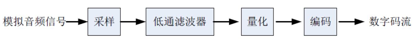
Figure 1 Digitization of audio signals
Sampling is the instantaneous amplitude value of the signal extracted at regular intervals. The number of samples per second is called the sampling frequency. Taking CD as an example, the sampling frequency is 44.1 kHz, that is, the analog signal is subjected to 44100 times in one second. As shown in Fig. 2b, the sampled signal becomes a plurality of dense points. The higher the sampling frequency, the higher the extracted point density and the more accurate the signal.
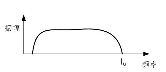
Figure 2a Original analog signal spectrum
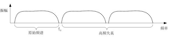
Figure 2b Specified spectrum
The signal sampled in Figure 2b, in addition to the original spectrum, additionally produces some high-frequency distortion to form a new spectrum. The spectrum of these distortions is center-symmetrical and n-symmetric (n is a positive integer), and its spectral distribution is the same as that of the original signal. The spectrum of the original signal can be recovered by filtering out the newly added excess spectrum using a low-pass filter (LPF).
According to the Nyquist sampling theorem: the sampling frequency fs is greater than or equal to twice the highest frequency fu of the sampled signal, the original signal without distortion can be recovered by the low-pass filter. If fs<2fu, some of the high-frequency distortion generated during the sampling process will overlap with the original spectrum. As shown in Figure 3, spectral aliasing distortion will occur. This superposition cannot be separated by a low-pass filter.
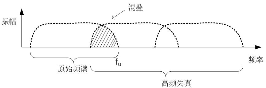
Figure 3 spectrum aliasing distortion
Therefore, the sampling frequency fs must be more than twice the highest frequency of the original signal, and the newly added spectrum and the original signal spectrum will not overlap each other. For example, the upper ear frequency of the human ear is 20 kHz, and the sampling frequency should be at least 40 kHz. However, the low-pass filter has a certain cut-off edge width, and the signal attenuation is gradually filtered out according to a certain rule. In order to better prevent high-frequency distortion, fs=(2.1~2.5) fu. The sampling frequency of the CD is 44.1 kHz, which is equal to 2.205 times that of 20 kHz.
The sampled amplitude values ​​are not integers and vary randomly. It is also necessary to convert these randomly varying amplitude values ​​to a value that can be expressed in a binary sequence by rounding off. This process is quantization, in bits (bits), as shown in the sample and quantization in Figure 4. The sampled value is 6.4. The amplitude is quantized and the integer 6 is taken. The sampled value is 3.6. The amplitude is quantized and the integer 4 is taken.
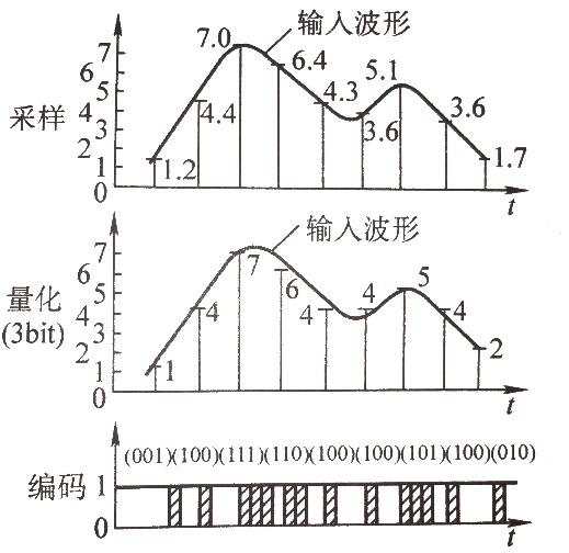
Figure 4 Three steps of A/D conversion
The quantized binary array is arranged in chronological order into a sequence of pulses that can be sequentially transmitted. This process is encoding. Since digital circuits are based on the on and off (1 and 0) states of the switch, the operation of the digital circuit can be greatly simplified. Therefore, binary coding has been widely used in digital technology.
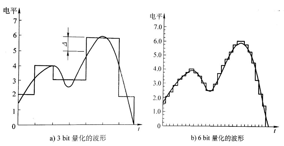
Figure 5 Relationship between quantization error and quantized bits
The more quantization levels, the smaller the quantization error and the better the sound quality. As shown in Figure 5, 3 bits are 23 binary numbers and 6 bits are 26 binary numbers. For audio signals, since the dynamic range is large and the required signal-to-noise ratio is high, the value of quantization is larger, usually 16 bits or even 20-24 bits.
Ethernet transmission method
Founded in 1980, Ethernet is a technology that can transfer data between interconnected devices. It has been widely used since its development, because of its low cost, fast speed and high reliability. We can send emails, pictures, sounds, videos and more via Ethernet. The Ethernet network uses CSMA/CD (Carrier Sense Multiple Access and Collision Detection) technology, which is a contention type media access control protocol. It works by: Listening to the channel before sending data is idle, if it is idle, it will send data immediately. If the channel is busy, it waits for a period of time until the information transmission in the channel ends, and then sends the data; if two or more nodes send a request at the same time after the last piece of information is sent, it is determined to be a conflict.
If you hear a conflict, stop sending data immediately, wait for a random time, and try again. We call this transmission mechanism "Best Effort" (that is, best effort), that is, when the data arrives at the port, it is forwarded on the principle of FlFO (first in, first out). The data is not classified. When the speed of the data entering the port is greater than the speed that the port can send, the FIFO enters the queue according to the order in which the data arrives at the port. At the same time, the data is dequeued in the order of the queue at the exit, and the advanced data will be First out of the team, the backward data will be out. The features of the CSMA/CD control method are as follows: the principle is relatively simple, and the technology is easy to implement. The workstations in the network are in an equal position, do not need centralized control, and do not provide priority control.
In Ethernet, we often encounter the term "bandwidth", which refers to the amount of data that can be transmitted per unit of time (generally 1 second). That is, the amount of information flowing from one end to the other within a prescribed time, that is, the data transmission rate. The basic unit of digital information flow is bit (bit), the basic unit of time is s (seconds), so bit/s (bits/second, also denoted by bps) is the unit describing the bandwidth, and 1bit/s is the basic unit of bandwidth. . It is not difficult to imagine that communication at a rate of 1 bit/s is very slow. Fortunately, we can use devices with fast communication speeds, such as a 56k modem to dial up the Internet with a telephone line. The bandwidth is 56000bit/s (1k=1000bit/s), and the telecom ADSL broadband Internet access is between 512kbit/s and 100Mbit/s. Today's Ethernet can easily reach more than 100 Mbit/s (1 Mbit/s = 1000 * 1000 bit / s = 1,000,000 bit / s).
Take Gigabit Ethernet (1Gbit/s) as an example: If the port bandwidth of the switch is 1Gbit/s, that is, 1000,000,000bit/s, it means that 1000,000,000 binary "bits" can be transmitted per second, then 1bit. The time taken is 1÷1000,000,000=1ns. That is, when the time interval between each bit (1 bit) is greater than 1 ns, no conflict will occur, as shown in FIG. 6.
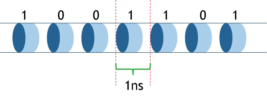
Figure 6
However, in Ethernet transmission, it is not transmitted in bits, but in "frames". As shown in Figure 7, a frame contains at least 46 Bytes (bytes) of data, then a minimum Ethernet frame is 72 Bytes; if the maximum data contained in a frame is 1500 Bytes, then the largest Ethernet The frame is 1526 Bytes.
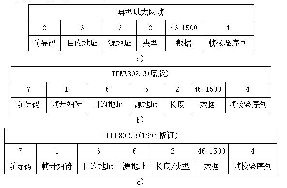
Figure 7 Ethernet frame structure
After receiving a frame, the network device and component need a short time to recover and prepare for receiving the next frame, that is, there is a gap between adjacent frames, IFG (Interframe Gap) frame spacing. The minimum value of IFG is 12 bytes, as shown in Figure 8.

Figure 8
We assume that the two frames of data are transmitted over a gigabit network (1 Gbit/s), so that the time interval between the two frames is greater than 96 ns without collision.
With the increase of network bandwidth, Gigabit has made some modifications to the data volume of the frame based on the traditional Ethernet. The carrier extension (Gamier Extension) method is used to extend the minimum byte to 512 bytes, that is, when the transmission frame length is less than 512 Bytes, the special character (0F) is padded. When many short frames need to be sent, if each frame is expanded to 512 Bytes, it will cause a huge waste of resources. Therefore, a method of frame bursting (Frame Bursting) is set, which can solve the problem. The first short frame uses carrier extension, and once the transmission is successful, the subsequent short frame is continuously transmitted until 1500 Byte. During this period, because the line is always in a "busy" state, no other stations will preempt the channel.
How does traditional Ethernet transmit real-time data streams (audio, video streams)?
Ethernet provides end-to-end delivery services with real-time features for data through the RTP (Real-time Transport Protocol) real-time transport protocol. RTP itself does not guarantee delivery, nor does it guarantee against out-of-order delivery. Therefore, if you want to sort all the data streams, you can't do without buffering the data. However, once the buffering mechanism is adopted, it will bring new problems - delay. So when we listen to songs and watch movies on the Internet, we will buffer them before we start playing. However, this buffer time is unacceptable in the field of professional audio and video transmission.
Digital audio signal requirements for Ethernet
Let's take CD as an example. Its sampling frequency is 44.1kHz and the number of quantization bits is 16bit. The time of each sampling is 1÷44.1×1000≈22.7μs. Our requirements for sound are continuous, that is, the data transmission interval under each sample is required to be no more than 22.7μs. In Gigabit network (1Gbit/s), the minimum time interval between two frames is only 96ns, which is much smaller than the 22.7μs we require. Under this bandwidth, we can transmit continuous uninterrupted audio signals. .
If we transmit data at a bandwidth of 1 Mbit/s, then the time occupied by 1 bit is 1 ÷ 1,000,000 = 1 μs, and the interval between two frames is 96 μs. At this time, if the CD digital audio signal is transmitted, there will be a problem of intermittent.
It is not difficult to see from the above two examples that as long as the network speed is fast enough, that is, the network has enough bandwidth, we can smoothly transmit digital audio signals on the network. But in most cases, since bandwidth is usually shared by multiple devices, we don't just use it to transmit one digital audio signal. We will transmit multiple digital audio signals at the same time, and also transmit mail, web pages, pictures, etc. Other data. And all senders do not have time-based flow control, then these senders will always send data as much as possible. In this way, the data streams from different devices will overlap in time, that is, the conflict we mentioned earlier. This will definitely affect the transmission of digital audio signals. In order to improve this transmission mechanism and improve part of the data transmission efficiency, Ethernet forwards through the QoS priority mechanism to ensure the transmission of a part of the data.
What is QoS?
QoS (Quality of Service) is an abbreviation of QoS. It includes guaranteeing the bandwidth of transmission, reducing the delay of transmission, reducing the loss rate of data and delay jitter. According to the ability to work, it can be divided into the following models:
1. The DiffServ (Differentiated Service) model classifies data of different services according to service requirements, prioritizes data by class, and then provides services differently. The data with high priority is forwarded first, and the data with lower priority is cached as a port. When there is no high-level data in the network, low-level data is forwarded, as shown in Figure 9.
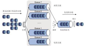
Figure 9
The AVB standard defines two traffic types, Class A and Class B. The class A flow priority is 5, and the B class flow priority is 4. When the two types of data are compared, the class A data stream is forwarded first.
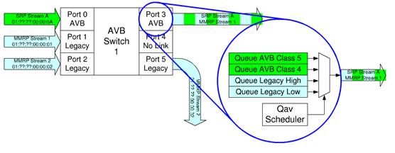
Figure 10
2. IntServ (Integrated Service) model, before the node sends data, it needs to apply for resource reservation to the network to ensure that the network can meet the specific service requirements of the data stream. It can provide both guaranteed service and load control services. Guaranteed services, guaranteed delays and bandwidth to meet application requirements; load control services to ensure that data can be served similar to when the network is not overloaded, even in the event of network overload.
It is highly probable that a large amount of data in the network will arrive at the port in an instant, ensuring that it is unthinkable for the service to provide QoS services for each data stream. Therefore, the IntServ model is difficult to apply to large-scale networks independently and needs to be used in conjunction with traffic shaping (Traffic Shaping).
Traffic Shaping
Traffic shaping is used to avoid data discarding on the Ethernet. Leaky Bucket is usually used to implement traffic shaping or rate limiting. Its main purpose is to control the rate at which data is injected into the network and smooth bursts of traffic on the network.
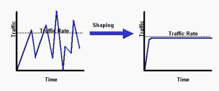
Figure 11 Schematic diagram of traffic shaping
The leaky bucket algorithm provides a mechanism by which burst traffic can be shaped to provide a stable flow to the network. Conceptually, the leaky bucket algorithm can be understood as follows: the arriving data is placed in a bucket with a leak at the bottom (data buffer); the data leaks out of the leaky bucket and is injected into the network at a constant rate, thus smoothing the bursty traffic. As shown in Figure 12.
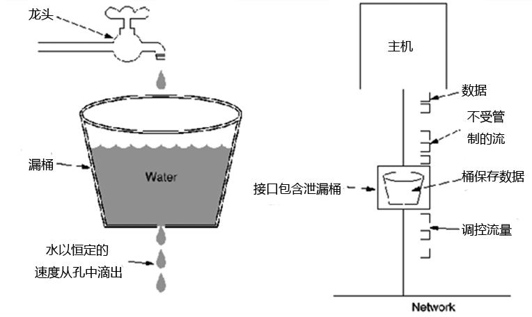
Figure 12 leaky bucket algorithm
The host outputs a packet to the network every time interval, thus producing a consistent data stream, smoothing the bursty traffic. The AVB standard defines two traffic types, Class A and Class B. The time interval of class A is 125 μs, and the time interval of class B is 250 μs. Class A requires that the flow have tighter latency and have a shorter observation interval, which means that its packets are smaller and transmitted more frequently.
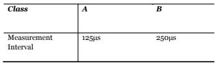
Figure 13
When the data streams have the same size, there is no problem in the mechanism of transmitting one data per interval. However, for variable length data, this working mechanism may have a problem. In this case, it is preferable to transmit a fixed number of bytes per time interval.
AVB has two streaming formats: AM824 and AAF. The AM824 supports 24bit audio, iec60958 audio encoding (SPDIF and AES3), SMPTE timecode and MIDI. There are three options for the sender AM824, "non-blocking (sync)", "non-blocking (aync)", and "blocking".
AM824 (non-blocking, synchronous), a typical AVB audio device uses this mode for transmission. One frame is sent per observation period, and each Ethernet frame always sends the same number of samples. When sampling at 48 kHz, each frame contains 6 samples; at 96 kHz, each frame contains 12 samples.
AM824 (non-blocking, async packetization). This mode may send a temporary Ethernet frame containing one or more samples due to the unsynchronized observation interval between the packetizer and the transmitter. A device that packs multiple clock domains is usually in this format. Because it can send temporary Ethernet frames, each frame contains 7 samples at 48 kHz; at 96 kHz, each frame contains 13 samples, which requires sufficient bandwidth. Apple Mac uses this mode.
AM824 (blocking) is a mode used by some Firewire devices because it is easier to pack and unpack. At 48 kHz sampling, each frame contains 8 samples; at 96 kHz, each frame contains 16 samples.
AAF is a new packing format defined in IEEE p1722a. It is less expensive than the AM824, requiring each frame in the data stream to have the same size and format, and allows 16-bit, 24-bit, and 32-bit quantization, as well as the number of samples per frame. The size and format of each frame is always the same.

Figure 14
From Figure 14, we can see the transmission of several typical AVB streams in 10 Gigabit (10 Gbps). For example: 48kHz sampling 32bit stereo audio stream, the actual required bandwidth is about 3Mbps, using Class A transmission interval, sending 8000 sets of data in 1 second (1÷8000=0.000125s=125μs), each group of data is up to 80 Frame composition. If each frame is transmitted according to the maximum data, the maximum frame mentioned in the above is 1526 Byte (as shown in Figure 7), plus the frame interval of each frame is 12 Bytes, a total of 1538 Bytes, which is equivalent to 12,304 bits (1 Byte = 8bit), each group of 80 frames is equivalent to 12,304×80=984,320bit, and 8000 sets per second are equivalent to 984,320×8000=7,874,560,000 bit/s≈7.87Mbps. Then at 10 Gbps bandwidth, if 75% of the bandwidth is reserved for transporting the AVB stream, 952 such data streams can be transmitted.
AVB can achieve full-duplex mode of operation. The amount of data per frame is related to the type of data transmitted. It is also related to the time interval. It is not difficult to see from Figure 14. The bytes occupied by different types of data are not an absolute one. Fixed value. Traffic shaping fixes the transmission time interval and frame size of real-time data streams (audio and video streams). When traditional asynchronous Ethernet data streams (mail, web pages, etc.) enter the network, will it affect the real-time data stream? ?
802.1Qav: Queuing and Forwarding Protocol (Qav)
The role of the Qav protocol is to ensure that traditional asynchronous Ethernet traffic does not interfere with the real-time data stream of the AVB. The AVB switch classifies the received data into different forwarding queues and re-prioritizes them. The real-time audio and video stream data has the highest priority. In order to avoid conflicts, two scheduling algorithms are needed, one is a credit based shaper transmission selection algorithm (CBS), and the other is a strict priority selection algorithm. Various common data are scheduled according to a strict priority algorithm, and when conflicting with the stream data, the CBS algorithm is called.
Time-sensitive real-time data stream forwarding uses pseudo-synchronous mode (Pseudo-synchronous), which relies on the 8 kHz clock provided by the Precision Time Synchronization Protocol (PTP). At every 125 μs time interval (1 ÷ 8000 = 0.000125 s = 125 μs), the Ethernet isochronous frame containing the AVB data is forwarded. Under the condition of preferentially guaranteeing isochronous frame data transmission, the service of ordinary asynchronous transmission is continued, which is Qav's priority management (Prioritize) and traffic shaping (Traffic Shaping).
When data is transmitted through multiple switches, even under the same bandwidth, the transmission time will be different due to different paths. How to ensure the same time interval in the entire network? A clock synchronization mechanism is also needed to synchronize all devices on the network to the same clock to improve the accuracy of AVB traffic shaping.
802.1AS: Precision Time Protocol (PTP)
The purpose of clock synchronization is to maintain a globally consistent physical or logical clock, or to align (synchronize) the clocks distributed throughout the system so that the information and events in the system have a globally consistent interpretation. The IEEE 802.1AS adopts the peer-to-peer mode. The time synchronization process is performed only between adjacent devices. The device itself synchronizes the time between the interfaces in the external mode without going through the internal switch board. It defines the master clock selection and negotiation algorithm, the path delay measurement and compensation algorithm, and the clock frequency matching and adjustment mechanism, which can be used to generate clocks and repair network audio and video systems. PTP defines a method for automatically negotiating the network master clock, namely the Best Master Clock Algorithm (BMCA). The BMCA defines the underlying negotiation and signaling mechanism for identifying the master clock (Grandmaster) within the AVB LAN.
The core of IEEE802.1AS is Time Stamping. When a PTP message enters or exits a port with IEEE802.1AS function, it will trigger sampling of the local real time clock (RTC) according to the protocol, and compare its own RTC value with the information of the master clock (Master) corresponding to the port. Path delay estimation and compensation techniques that match the RTC clock value to the PTP domain. When the PTP synchronization mechanism covers the entire AVB LAN, each network node device can exchange accurate real-time clock adjustment and frequency matching algorithms through periodic PTP messages. Eventually, all PTP nodes will be synchronized to the same "Wall Clock" time, the Grandmaster time. The message exchange process is as follows:
1. The Master sends a Sync message and notes the local transmission time t1 of the message.
2. Slave receives the Sync message and notes the local time t2 at which it received the message.
3. Master has two ways to tell Slave the time t1 of the Sync message.
1) Embed t1 time into the Sync message, which requires some kind of hardware processing to get high precision.
2) Send in the subsequent Follow_Up message 4. Slave sends a Delay_Req message to the Master, and writes the transmission time t3.
5. The Master receives the Delay_Req and notes the arrival time of the message t4.
6. The Master sends a Delay_Resp message to tell Slave t4.
Using these four times, the clock difference between the Master and the Slave can be calculated, provided that the link is symmetric, ie the transmit and receive delays are the same. The calculation formula is:
Offset = ((t2 - t1) - (t4 - t3))/2
One_way_delay = ((t2 - t1) + (t4 - t3))/2

Figure 15
In a network environment of up to 7 hops, theoretically PTP can guarantee clock synchronization errors within 1 μs. Since the serial connection switch affects the symmetry of the delay and reduces the synchronization accuracy, a symmetric link design is recommended when constructing the AVB network.
Once the master clock is selected, the PTP devices of all LAN nodes will use this master clock as the reference value. If the Grandmaster changes, the entire AVB network can also determine the new master clock in the shortest time through the BMCA, ensuring that the entire network remains time synchronized. .
The protocol specified by the standard strictly guarantees the simultaneous transmission of real-time data streams in fixed or symmetric transmission media based on Ethernet delays. It includes maintenance of the time synchronization mechanism when the network is up and running, adding, removing or reconfiguring network components and network failures, providing a perfect low-latency, low-jitter clock for Ethernet, ensuring high-quality bandwidth. The service arrived quickly.
After ensuring time precision, if the bandwidth is insufficient, the leaky bucket will be filled quickly and there will be data overflow. If the audio and video data overflow is discarded, there will be intermittent problems, and some sounds or pictures may be lost. Therefore, we also need to ensure that there is enough bandwidth to transmit real-time audio and video data streams.
802.1Qat: Stream Reservation Protocol (SRP)
To provide guaranteed QoS, the flow reservation protocol ensures end-to-end bandwidth availability between real-time data stream devices. If the required path bandwidth is available, all devices (including switches and end devices) on the entire path will lock this resource. SRP-compliant switches can use 75% of the entire network's available bandwidth resources for AVB links, leaving 25% of the bandwidth reserved for traditional Ethernet traffic.
In SRP, the provider of the streaming service is called Talker, and the receiver of the streaming service is called Listener. The streaming service provided by the same Talker can be received by multiple Listeners at the same time. SRP allows only one-way data flow from Talker to Listener to be guaranteed.
As long as the bandwidth resources from Talker to any of the multiple Listeners can be negotiated and locked, Talker can begin to provide real-time data streaming services. The periodic periodic state mechanism of the SRP maintains the registration information of the Talker and the Listener, and can dynamically monitor the status of the network node and update its internal registration information database to adapt to the dynamic change of the network topology. Both Talker and Listener can join or leave the AVB network at any time without unrecoverable effects on the overall functionality and state of the AVB network.
1722: Audio/Video Bridging Transport Protocol (AVBTP)
AVBTP defines the Layer 2 data format required for real-time data stream services in the LAN, and the establishment, control, and shutdown protocols for real-time data streams. AVBTP establishes a virtual link with low latency between physically separated audio and video codecs.
Various compressed and uncompressed original audio and video data streams are packaged via the AVBTP protocol (filling the stream ID reserved by the SRP, timestamps generated by the PTP, and media types, etc.), through the AVBTP-dedicated Ethernet frame type. Multicast is performed, sent from the provider of the streaming service (Talker), forwarded by the AVB switch, and then received and unpacked, decoded, and output by the receiver (registerer) registered with the real-time data stream service.
AVBTP sends this frame every 125μs, it is always the same size data stream. Each stream can consist of 1-60 channels and can support up to 64 streams.
AVB - Ethernet Audio Video Bridging is a set of protocols based on the new Ethernet architecture developed by the IEEE 802.1 Task Group in 2005 for real-time audio and video transmission protocol sets. In addition to the related protocols described above, it also includes:
802.1BA: Audio Video Bridging Systems
The AVB system standard defines a set of presets and settings used in the production of AVB-compatible devices, so that users without network experience can also establish and use the AVB network without having to configure them cumbersomely.
1733: Real-Time Transport Protocol (RTP)
RTP is a protocol based on Layer 3 UDP/IP network. In order to utilize the performance of Layer 2 AVB in IP-based Layer 3 applications, IEEE 1733 extends RTP to provide time synchronization in the LAN through bridging and routing. Delay guarantee and bandwidth reservation services to provide real-time data stream transmission. It involves protocols such as packet format, flow establishment, control, synchronization, and shutdown.
1722.1: Responsible for device discovery, enumeration, connection management, and mutual control between 1722-based devices. Used for AVB device discovery, enumeration, connection management, firmware upgrades, etc.
TSN (Time Sensitive Network) time sensitive network
In November 2012, the IEEE 802.1 Task Force officially renamed AVB to TSN, the Time Sensitive Network time-sensitive network. In other words, AVB is just an application in TSN.
In addition, TSN is also used in the industrial field of automotive control, commercial electronics, real-time monitoring or real-time feedback. If you want to know more about the TSN network, you can visit the AVnu Alliance website at http://avnu.org/
There are a few different types of slip rings, but the most common type is called a cap slip ring. Cap slip rings have a cylindrical housing with an internal flange that fits over the end of the shaft. They typically have 6 or 12 channels and are available in a wide range of sizes.
Cap slip rings are used to provide electrical power and signals to and from rotating equipment. The channels on the slip ring allow for the passage of current and/or data signals through the ring. This allows for the rotation of devices such as antennae, radar dishes, and wind turbines without having to interrupt or disconnect the power or signal lines.
Cap slip rings are very reliable and can handle high speeds and heavy loads. They are also easy to install and maintain.
In the modern world, companies are always looking for ways to improve the efficiency of their machines and operations. Oubaibo offers a variety of products that can help improve your machine's performance. Their Cap Slip Ring allows for high-speed rotary unions, while their high-pressure swivel joints can handle even the most strenuous industrial applications. With so many options available, there's sure to be an Oubaibo product that can improve your machine's performance.
Cap Slip Ring,High Speed Rotary Unions,High Pressure Swivel Joints,High Pressure Swivel Joint
Dongguan Oubaibo Technology Co., Ltd. , https://www.sliproubo.com