introduction
This article refers to the address: http://
This paper mainly designs a smart car that recognizes the road independently. The whole system adopts 16-bit single-chip microcomputer mc9s12dg128. The model car itself has differential and rear-wheel drive. It needs to design and complete the automatic control system based on single-chip microcomputer to make the model car run autonomously on the closed runway.
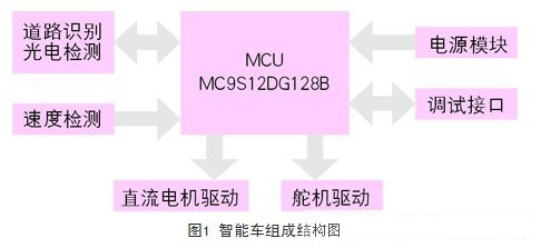
The car model and the controller form an automatic control system. As shown in Fig. 1, the system hardware is based on the single chip microcomputer, equipped with sensors, actuators and their driving circuits, and the information processing and control algorithm is completed by the single chip software. The system design requires the MCU to combine the rapid judgment of the path, the corresponding steering servo motor control and the control of the DC drive motor.
The design of the smart car is based on the premise of ensuring the reliable operation of the model car, with the principle of simple circuit design and high vehicle flexibility. The two major points of design are the layout and circuit design of the photoelectric sensor, and the design of the routing control algorithm.
The second section of this paper mainly introduces the circuit design and layout of the photoelectric sensor, which is the key to signal acquisition, which is equivalent to the "eye" of the smart car. The third section mainly introduces the routing control algorithm, which is the core of control, which is equivalent to The "mind" of the smart car; finally, in the fourth section, the hardware, software design and experimental situation of the smart car are generally explained.
First, photoelectric sensor
Photoelectric sensor selection and circuit design
The photoelectric sensor is located at the forefront of the smart car and acts as a pre-determined path. The light emitted by the light has different reflectivity to white and black, so different voltage values ​​can be obtained. After adopting the single chip microcomputer, the voltage is used to judge the position of the black line by a certain algorithm, thereby controlling the rotation of the steering gear. This method is easy to implement, fast in response, good in real-time, and low in cost.
This paper chooses the reflective infrared sensor tcrt5000 which is basically suitable for cost performance. The design of infrared photoelectric sensor circuit is various. Because the algorithm uses the sensor array experience judgment method, the digital output sensor circuit is used for control, as shown in Figure 2.
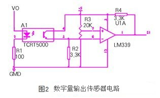
The photocell adopts pulse modulation type illumination, that is, vo is a pulse voltage generated by the oscillating circuit, so that the filter is free from interference. Although the circuit is relatively complicated, it is enough to ensure stable driving of the model car.
Research on Photoelectric Sensor Layout
The layout of the photocell array directly affects the routing effect of the smart car. In general, a typical layout has a "one" shape layout and a "w" shape layout.
The so-called "one" shape layout is to arrange multiple sensors in accordance with the "one" word. This type of sensor layout is the most common and the algorithm is theoretically easy to implement. The downside is that there is almost no predictive power on the curvature of the track. Therefore, this layout is generally not used.
The "w" layout is to arrange multiple sensors in a "w" shape. The “w†layout is distributed in two rows, so that the smart car has a certain predictive function for the curve. This kind of prediction function is especially reflected in the straight road entering the curve. When the rear row of sensors is still in the straight, the front row of sensors has entered the corner. The downside is that the complexity of the control algorithm is increased. When judging the direction of rotation of the steering gear, the last detection data is often needed. The possibility of empirical judgment also increases as the number of sensors increases.
Photoelectric sensor layout simulation
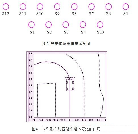
After many simulation experiments, the layout and number of sensors were finally determined. Using the "w" layout shown in Figure 3, there are 13 sensors, 8 in the front row, 5 in the back row, and 3.5 cm in the front and rear rows. Set this spacing to give it a predictive function on the track. The specific layout and simulation results are shown in Figure 4.
Second, the line control algorithm
In this paper, empirical feedback control is adopted, that is, on the basis of common experience control, the idea of ​​pid control is added, three control constants of proportional, integral and differential are introduced, feedback is implemented, and the control method of integral separation is adopted.
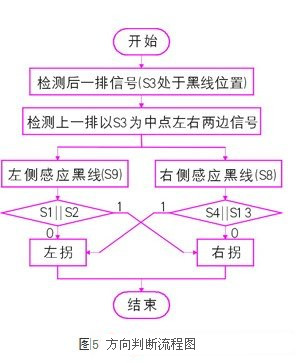
The line control algorithm uses the integrated detection signals of the two rows of sensors before and after to infer the precise steering of the model car and the specific vehicle speed. The direction judgment method is as follows: as shown in Fig. 3, firstly determine the situation of the five sensors in the lower row, assuming that s3 is at the black line position, and then observe the upper row of eight sensors, at this time s3 divides the upper row of sensors into left and right sides, due to the phase The distance between the two adjacent sensors is slightly larger than the width of the black line, so only two sensors can detect the black line at any time, so that the steering of the model car can be basically judged based on the analysis of the upper and lower rows of sensor signals. For example, when a black line is detected at a certain time s3 and s8, it can be roughly judged that the model car should be turned to the right, and the steering angle and the general angle of the steering gear can be judged according to the angle between the connection of the two sensors and the vertical direction.
However, it should also be noted that when the car model enters the left corner, it may also be the case that s3 and s8 jointly detect the black line. In this case, it is necessary to check the sensor signal at the previous moment, that is, to detect s4||s13. In the case, if the result of s4||s13 is 1, it is considered that the car model should be turned left. If the result of s4||s13 is 0, it should be turned right. The flow of the primary direction judgment is shown in FIG. 5.
Two arrays are created in the program, one storing each detected signal and the other storing the current signal after the control is implemented as historical data. Adding this idea with historical record judgment makes the control more precise.
In addition to the above judgment rules, there are two situations to consider. That is, only one sensor detects the black line and the situation of the cross track. For the case where only one sensor detects a black line, it is also necessary to check the sensor signal at the previous moment. For example, only s6 detects the black line at a certain moment. If the black line is detected at the previous time s5, the vehicle model turns left. At the moment s7 detects the black line, the car model turns right.
For the case of a cross track, it is "filtered" off with a "filtering" idea. When encountering a cross track, it is inevitable that several sensors in the same row will detect the black line at the same time. At this time, the model car is given a command to make it straight forward, and the cross track is eliminated.
This is the thread-based control algorithm based on the empirical logic of the system. On this basis, through continuous experiment adjustment of each parameter, a better control effect can be achieved.
Third, the experimental results
hardware design
Motor drive circuit
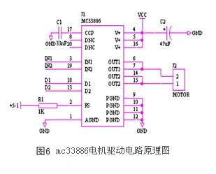
The motor drive uses mc33886 as the driver chip. The principle is shown in Figure 6. By sending pwm waves to the in1 and in2 ports to control the forward and reverse rotation of the motor, the forward rotation is accelerated to the smart car, and the reverse speed is reversed. Changing the duty cycle of the pwm wave controls the rate of rotation of the motor.
Speed ​​detection circuit
In this paper, the incremental photoelectric encoder is used to measure the vehicle speed. The frequency of the output pulse is proportional to the rotational speed. The frequency of the pulse can be obtained by measuring the number of pulses or the pulse period per unit period, which has high precision.
Power conversion circuit
The smart car system is equipped with a 7.2v battery that can directly power the DC motor. The required voltage for the microcontroller, photoelectric sensor and photoelectric encoder is 5v, and the servo servo is 6v. These voltages are adjusted by the 7.2v battery.
The single chip microcomputer and the photoelectric encoder are powered by the voltage regulator chip 7805 to output 5V voltage. The number of photoelectric sensors is large, the power consumption is large, and the stability of the power supply is higher. Therefore, the high-efficiency chip lm2575 is used to supply power thereto. The chip that supplies the servos is a low-dropout adjustable output three-terminal linear regulator lm1117, which provides functions such as safe operation protection on the chip.
software design
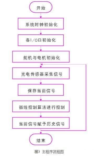
The software design is implemented by modules. The main program includes clock initialization, i/o port initialization, servo motor initialization, acquisition signal and control algorithm. The program flow is shown in Figure 7.
Fourth, the experimental results and analysis
In the process of program development, the s12 core development board provided by the organizing committee is completely adopted. It is the smallest system composed of mc9s12dg128 single-chip microcomputer. The mc9s12dg128 belongs to the hcs12 series of single-chip microcomputers and is a high-performance 16-bit microcontroller introduced by Motorola. It can provide 32-512kb third-generation flash embedded memory with bus speeds up to 50mhz and peripheral clocks up to 25mhz. It also has coding benefits, on-chip error correction capability, and is upwardly compatible with the mc68hc11 and mc68hc12 structure codes. The mc9s12dg128 microcontroller has 112 pins, of which the cpu-related pins are compatible.
The s12 development board has a reset circuit, a crystal oscillator and a clock circuit that constitute the minimum system, an rs-232 driver circuit for the serial interface, and a +5v power socket. The developed monitoring program has been written in the microcontroller. 8 small lights are used to debug the application system. All i/o ports of the microcontroller are brought out by two 64-pin European plugs.
During hardware debugging, the function of each module is tested separately, and the photoelectric sensor is mainly adjusted. When the black and white line is perceived, the output signal should be different. When the white line is sensed, the output of the comparator is low, and when the black line is perceived, the output is high. When debugging software, you can use the bdm development tool to display the data in its internal memory when the microcontroller is running.
Through the joint debugging and experiment of hardware and software, some problems have arisen, but the effect is greatly improved by perfecting the program and reassembling the model. The final model can be run on the runway, but there are still problems such as high power consumption and steering delay.
Conclusion
Based on the principle of automatic control, this paper uses the road deviation signal of the pathfinder module to realize the tracing tracking of the smart car, and uses the pwm technology to control the rotation speed of the motor and the steering of the steering gear.
This paper focuses on the layout of the "w" shape of the photoelectric sensor and the routing control algorithm, which are the key to ensure the intelligent operation of the smart car. The “w†layout allows the smart car to have road prediction capabilities, while the line control algorithm makes the car body turn quickly and correctly.
Through the simulation and experiment of the smart car, the whole system scheme is feasible, and the system control strategy and hardware and software are basically reasonable. In terms of control, although the classic pid control has good control effect on motor speed regulation, the pid control effect is affected because the dynamic model of the vehicle model changes due to different vehicle conditions. Later, fuzzy control can be considered to make the algorithm More intelligent, the system is more adaptable.
Zener Diode, the English name Zener diode, also known as Zener diode. By using the reverse breakdown state of the pn junction, the current can be varied over a wide range and the voltage is substantially constant, and the diode that acts as a voltage regulator is fabricated. [1] This diode is a semiconductor device that has a very high resistance until the critical reverse breakdown voltage. At this critical breakdown point, the reverse resistance is reduced to a small value in this low resistance region. The current is increased and the voltage is kept constant. The Zener diode is binned according to the breakdown voltage. Because of this characteristic, the Zener diode is mainly used as a voltage regulator or voltage reference component. Zener diodes can be connected in series for use at higher voltages, resulting in higher regulated voltages in series.
Zener Diode
Power Zener Diode,Zener Diode,Zener Diode Regulator,Zener Diode 56V
Dongguan Agertech Technology Co., Ltd. , https://www.agertechcomponents.com