1. Introduction
The technical level of CNC machine tools and the percentage of the output and total ownership of metal cutting machine tools are one of the important indicators for measuring a country's national economic development and the overall level of industrial manufacturing. CNC lathe is one of the main varieties of CNC machine tools. It occupies a very important position in CNC machine tools. It has been widely valued by countries in the world for decades and has been rapidly developed. The spindle is an important part of the lathe. It plays an important role in improving processing efficiency, expanding the range of processing materials, and improving processing quality. Most economical CNC lathes cannot be automatically shifted. When shifting is required, the machine tool can only be stopped and then shifted manually. Most of the main transmission systems of full-function CNC lathes use stepless speed change. At present, there are two main types of continuously variable transmission systems: frequency conversion spindle system and servo spindle system. DC or AC spindle motors are generally used. Drive the spindle through belt drive, or through the belt drive and the reduction gear in the spindle box (to obtain greater torque). Due to the wide range of speed regulation of the spindle motor and the stepless speed regulation, the structure of the spindle box is greatly simplified. At present, due to the high cost performance of the inverter, the inverter is very commonly used in lathes. With its unique performance and superior cost performance, Delta M series inverters have rapidly emerged in the application of CNC machine tools and become a powerful force in the current market.
Second, the introduction of the characteristics of the inverter
1. Small size, it is a mini product and takes up less space in the control cabinet;
2. The control method is sine wave SPWM (provides vector control without speed feedback), the control performance is greatly improved compared with the previous VF control method, especially at low speed torque to meet the needs of the machine tool spindle, the starting torque can be 5HZ Reach more than 150%;
3. Carrier frequency range 0-15KHz, reduce the electromagnetic noise of the motor;
4. Provide standard 0-10V analog interface (input impedance 47Kohm, output impedance 250Kohm), compatible with most CNC system interfaces, strong versatility;
5. Strong overload capacity, more than 150% of rated output current exceeds one minute;
6. Provide multi-functional output terminal signals, such as zero speed signal, running signal, speed arrival signal, fault indication, to meet the system monitoring of spindle speed status;
7. Automatic torque compensation to meet the processing requirements of the machine tool spindle at low speed;
8. Provide three sets of abnormal records for maintenance personnel to understand the actual operation status of the machine tool spindle from the side;
9. Motor parameter auto-tuning function, online identification of motor parameters to ensure the stability and accuracy of the system.
3. Debugging environment, wiring and debugging methods
The customer's optional motor is 3.0KW / 50Hz / 380V, the inverter model is VFD037M43, and the braking resistor is 400W / 150ohm.

The AVI / GND terminal of the frequency converter provides the speed analog quantity with the numerical control system, AVI connects the positive signal of the numerical control system analog interface, GND connects the negative signal, the signal is 0-10V analog voltage signal, and controls the spindle speed. M0 / M1 / ​​GND is the forward / reverse signal terminal of the inverter. Normally, the CNC system sends forward signal FWD or reverse REV to drive the intermediate relay. The normally open contact of the intermediate relay is connected to the inverter M0 / GND or M1 / GND, to control the forward and reverse of the inverter.
In the process of parameter adjustment, you need to pay attention to:
1. P00 parameter is to select the main frequency input setting source, set to analog signal 0-10V input (1);
2. P01 parameter is set for the source of the running signal, and set to the external terminal signal control (2);
3. The maximum operating frequency selection of P03 corresponds to the output frequency of the inverter when the analog signal is input at 10V. Since the speed is adjusted within the range of 0-3500rpm, after calculating the mechanical reduction ratio, this parameter needs to be set to 184HZ;
4. P04 and P05 are set according to the motor nameplate, P04 = 50Hz, P05 = 380V;
5. P10 and P11 are acceleration time and deceleration time, according to customer requirements, P10 = 5S, P11 = 5S;
6. P105 is the choice of control mode, you need to select vector control, P105 = 1;
Special attention should be paid, because the vector control needs to provide motor parameters (impedance), the inverter provides motor parameter auto-tuning function P103, select P103 = 2, and the inverter will automatically run through the panel run key. In the automatic operation process, in addition to calculating the motor parameters, it can also detect the no-load current. These parameters are very important for the vector control to show high performance. This process will last for more than ten seconds. Before executing the auto-tuning function, make sure that there is no connection on the motor side, including the reduction belt.
4. Debugging results
The test results are as follows:
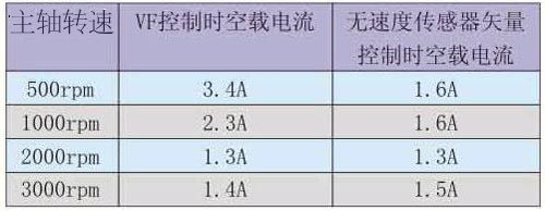
Table 1 No-load current test results
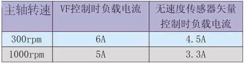
Table 2 Load current test results
It can be seen from the above table that in the frequency range of constant torque output (0-50Hz), the no-load current of vector control is almost half of that of VF control, and the current under load is also smaller than VF; At the beginning, there was a significant speed drop, and there was a relatively large difference between the no-load speed and the load speed. Compared with vector control, although the spindle speed will also decrease at the initial stage, the decrease value is small, and the speed will rise quickly. The difference between the final no-load speed and the load speed is not very obvious. After the above debugging, compared with the original VF control, the performance has been greatly improved, no matter from no-load current, low-speed torque, or speed change, the effect is very obvious, and can fully meet the needs of CNC machine tools.
BLPS laser safety protective device is designed for personal safety used on hydraulic bender.
The dynamic test technology it used has passed the Type 4 functional safety assessment by TUV, and get the national invention patent. The product reaches the advanced technological level of similar products.
BLPS laser safety device provides protection zone near the die tip of the bender to protect fingers and arms of the operator in close to the upper mold die tip. It is the most effective solution so far to preserves the safety and productivity of the bender.
Press Brake Protection,Laser Safety Guard Device,Laser Guarding Device,Press Brake Laser Guard,Press Brake Guarding Systems,Press Brake Guarding
Jining KeLi Photoelectronic Industrial Co.,Ltd , https://www.sdkelien.com