Keywords: LAN, bridge, E1
1 Introduction With the rapid development of computer networks, more and more enterprises have established their own local area networks. For a small business, it is convenient to use Internet technologies and products on its own local area network to establish a dedicated corporate network (ie, intranet). For a large company or a system, because the geographical distribution of its branches and subordinate organizations is not centralized, the connection between the various LANs of the entire company or system becomes a key issue.
The E1-LAN bridge device introduced in this article uses the E1 line of the telecommunications department to interconnect the local area network. The communication reliability of the E1 line itself is guaranteed. With the use of the transmission network and mature technology of the telecommunications sector, the data on the E1 line can be transmitted over a distance of tens of kilometers to thousands of kilometers, and can even be transmitted across countries. The system first uses the bridge module to extract the data that needs to be sent out on the local area network, and then inserts it into the PCM time slot for propagation. Depending on the number of time slots selected, the transmission rate can be selected from 64 kbps to 1984 kbps. If you connect multiple E1 lines, you can even reach the 10Mbps transmission rate of the local area network. And, using the allocation of PCM time slots, one E1 line can be used to connect multiple LANs.
2 Introduction to chip (module) selection
2. 1 bridge module IRâ”ETH
IR-ETH is an Ethernet bridge module of RAD, and it is a key device in this equipment. IR-ETH has the following functions and features: fully compatible with IEEE802.3 / Ethernet V. 2. Provide UTP (10Base T) or BNC (10Base2) LAN interface, provide TTL WAN interface (synchronous serial interface), WAN interface data rate can reach 40Mbps, can filter and send 15,000 frames per second Data, built-in 256-frame cache, built-in MAC table can store 10,000 MAC addresses, and can automatically learn and update.
2. 2 E1 interface chip MT9075
MT9075 is a single-chip E1 transceiver of MITEL, which integrates an enhanced PCM32 / 30 framer and a line interface unit (LIU). MT9075 has the following features: Intel or Motorola non-multiplexed parallel processor interface, provides ST-BUS / GCI2048 Mbit / s data / signaling bus interface, optional transmit / receive jitter attenuator, flexible receive buffer that can control the sliding direction (2 frames), can work in synchronous mode and free mode (main mode), low jitter phase-locked loop is used to generate the clock, provides enhanced performance monitoring function, the dynamic range of LIU is 20dB.
2. 3 main control DSPTMS320F206
This system uses TI's TMS320F206 as the main controller. The main features of TMS320F206 are: instruction cycle is 50ns @ 5V (20MIPS), provides three external interrupts, 32K × 16 Flash Memory is integrated on-chip, and 544 × 16 is integrated on-chip The dual-port RAM integrates 4K × 16 RAM on-chip, and the maximum external address space of 224K × 16. The integrated peripheral components mainly include: 16-bit timer, oscillator, phase-locked loop, full-duplex asynchronous serial port, enhanced synchronous serial port, with four-level FIFO, and 6 general-purpose I / O pins.
3 system design scheme The system block diagram is shown as in Fig. 1.
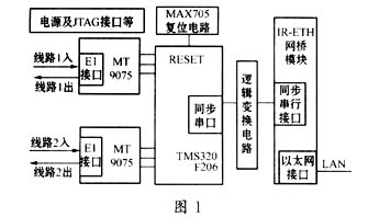
3.1 External interface As shown in Figure 1, the system uses two external interfaces, E1 line interface and LAN interface. Because the MT9075 integrates the line interface unit LIU, you only need to add a transformer and a small amount of resistance and capacitance externally to connect the E1 coaxial cable. On the LAN interface side, the IR-ETH module has directly provided a LAN interface, and can be directly connected to the LAN through a network cable without other peripheral components.
The data transmission between the bridge module IR-ETH and the E1 chip MT9075 and the data splitting and reassembly are controlled and realized by DSP (TMS320F206).
3. The interface of DSP and bridge module The bridge module has a wide area network interface of synchronous serial mode, connect the synchronous serial port of DSP with it, then you can send and receive the data of bridge module through DSP. Because the timing and logic of the IR-ETH synchronous serial port is slightly different from the DSP synchronous serial port logic, a logic conversion circuit is used for adjustment. In the connection between the two, the giving of the clock is more critical. When the synchronous serial port of the DSP receives data, it needs to use an external clock signal to synchronize; and IR-ETH does not provide such a clock signal. On the contrary, it also needs an external clock to synchronize the transmission of its synchronous serial port. Therefore, we use the CLKOUT1 pin of the DSP to generate a clock signal, which is sent to the CLKR of the DSP and the TXC of the bridge module. The DSP's synchronous serial port sends its own clock through CLKX when sending data. We only need to invert it to the RXC pin of the bridge module.
When the bridge module has ready data to send, it will send a request by pulling the RTS pin low. We connect RTS to DSP's interrupt pin INT2, which triggers DSP's interrupt to read data. Send a response to the CTS of the bridge module through the IO1 pin of the DSP, informing the bridge module to start sending data.
3.3 Interface of DSP and E1 chip By connecting the INT / MOT pin of E1 chip MT9075 to high level, we set MT9075 in Intel non-multiplexed parallel processor interface mode. Connect the data bus, address bus, read and write signals, and chip select signals between the DSP and MT9075 to read and write the registers inside the MT9075. The internal registers of MT9075 include control registers and data registers (memory). By setting the control register, the MT9075 works in the correct mode; by reading and writing the data register, you can easily get the data on the E1 line, and you can also easily send data to the E1 line.
In order to ensure that the data read from the data register of MT9075 is neither missing nor repeated, the RxFP pin of MT9075 is connected to an interrupt pin INT1 of DSP. In this way, after MT9075 receives a frame of data, the pulse of RXFP can be used as an external interrupt signal of DSP, triggering the interrupt handler in DSP to read data from MT9075 data register.
In order to deal with the abnormal state of MT9075 in time, the interrupt pin of MT9075 is connected to the highest level of interrupt pin NMI of DSP. In this way, when an abnormal state occurs in MT9075, the corresponding program in DSP can timely determine the type of error by querying the register of MT9075 and deal with it accordingly.
If the device is used at both ends of the E1 line, only one E1 chip is needed. As shown in Figure 2, A and D two devices. If the device is in the middle of the E1 line and intercepts the E1 line, in order to ensure the smoothness of the entire E1 line, two E1 chips are required. Each device can be allocated several timeslots in the E1 line. Each device only reads the data in these timeslots, and only sends data to these timeslots. Other data can be transferred to the next node through the E1 line as it is by setting the register of MT9075. As shown in Figure 2, B and C equipment. 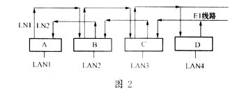
Clock synchronization is a key to ensure that the E1 chip can work reliably. Here is a brief description of how to achieve clock synchronization in this device.
Taking Figure 2 as an example, there can only be one master clock in the entire device. Set the sending part of device A to work in the master clock mode, and the line LN1 is connected to the sender of device A. Then the reception of B, C, and D should extract the clock from the E1 line, and the extracted clock is used when sending data. Especially for the D device, the clock extracted from LN1 will be used to send data to LN2. In this way, the entire system can be synchronized.
The allocation of time slots, the identification of device types, and the 41 mode of clock synchronization are all set by DIP switches. The working status of the equipment is indicated by light-emitting diodes.
The workflow of the entire system can be summarized as follows:
(1) After the system is powered on, the DSP runs an initialization program: read the configuration of the DIP switch, set the MT9075 register, initialize the MT9075; and initialize the DSP itself as necessary. IR-ETH module can initialize itself after power on.
(2) When the bridge module receives data that is not sent to the local area network, it encapsulates the data according to the HDLC format, and then sends a request by pulling the RTS pin level low, thereby triggering the DSP interrupt. The DSP sends a response to the CTS of the bridge module through the IO1 pin, and then the bridge module begins to send data through the synchronous serial port. The synchronous serial port of the DSP receives the data and writes it to the data register corresponding to the corresponding time slot of the MT9075 according to the configuration. MT9075 sends the data in the data register to the corresponding time slot in the E1 line.
(3) After receiving the last frame of data from E1, MT9075 in the other end device triggers the DSP interrupt through the RxFP pin. The DSP program reads the data of the corresponding time slot from the data register in MT9075 according to the configuration. Then send the data to IR-ETH module through the synchronous serial port of DSP. After receiving the data, the bridge module decodes it according to the HDLC protocol, restores it to the data format on the local area network, and then sends it to the local area network through the local area network interface. In this way, the data from the two LANs can communicate with each other, and the two LANs with very different geographical locations have actually become a large LAN.
4 Conclusion This device can realize the interconnection of 802.3 LAN in the data link layer of the ISO seven-layer model, and can provide a transmission rate that is more than thirty times faster than the MODEM. Even if the local area networks are far apart in geographical location, after being connected by this bridge system, the user will see a large local area network. The user's operation of the data on the remote LAN will be the same as that of the local LAN. After planning the IP address, popular services such as http, ftp, and telnet on the Internet can be used transparently on the bridge system. In this system, the E1 line between the two bridges is provided by the telecommunications department. With the help of the mature technology of the telecommunications department, it is theoretically possible to realize data transmission on a global scale. The network formed by this equipment does not need to borrow the public Internet, and has good confidentiality. This device has a wide range of application prospects in the establishment of enterprise private networks and remote monitoring.
2 Zhu Shihua. Principle and application of program-controlled digital exchange. Xi'an: Xi'an Jiaotong University Press, 1996
3 Fan Changxin, etc. Communication principle. Beijing: National Defense Industry Press, 1998
Pad Mounted Transformer,Wind Power Substation,Step-Up Wind Power Sustation,Step Up Transformer
Hangzhou Qiantang River Electric Group Co., Ltd.(QRE) , https://www.qretransformer.com