Keywords: HART communication protocol, HART modem, intelligent field device, pressure measurement
Remote data collection and control play an important role in industrial field monitoring. In traditional data acquisition and control (SCADA) systems, on-site measurement and control equipment usually use analog signals. With the development of computer technology, most field devices used to complete measurement and adjustment contain embedded microprocessors, that is, intelligent field devices. It means low measurement cost and high-precision data. Fieldbus technology establishes data transmission and information exchange between field devices and remote monitoring computers. It replaces traditional analog signals with digital signals and is an open bus network standard. The HART communication protocol belongs to the fieldbus category. In this paper, the HART communication protocol is used to design a gas pressure measurement scheme for urban pipelines.
1 HART Communication Protocol Introduction HART (Highway Addressable RemoteTransducer) communication protocol was proposed by Rosemount for its smart transmitter in 1986. With the continuous development and expansion of its application range, the HART User Group was established in 1989, and the HART Communication Foundation (HCF) was established in 1993. Unlike other fully digital fieldbus technologies, HART communication protocol relies on traditional analog signal transmission technology. It uses FSK technology, a carrier frequency signal is superimposed on the 4 ~ 20mA analog measurement signal, so that the two-way communication of analog signals and digital signals can be carried out simultaneously without interfering with each other. The HART communication protocol can also communicate in an all-digital manner on one communication line, supporting 15 field devices to complete signal measurement, device configuration, device calibration, and status detection. The HART communication protocol has a similar architecture to other fieldbuses. It refers to the open interconnection model of the International Organization for Standardization and corresponds to the 1, 2, and 7 layer protocols of the OSI protocol (physical layer: Bell202, data link layer: HART communication protocol specification, application layer: HART command).
The physical layer stipulates that HART communication adopts Bell202 protocol based on FSK. The baud rate is 1200bps, logic 0 is 2200Hz, logic 1 is 1100Hz. Since the average value of the sine wave signal is zero, the HART communication signal will not affect the average value of the 4-20mA signal. There are two types of networking methods: "point-to-point network" and "multipoint network". If field devices are required to transmit digital and analog signals at the same time, only point-to-point methods can be used. The analog signals of different field devices cannot be identified in a multipoint network. The data link layer specifies the communication data structure. Each character is composed of 11 bits, a start bit, 8 data bits, a parity bit and a stop bit. The number of bytes of HART data is not constant. Each frame of HART data has a vertical check byte. Figure 1 shows an example of a short frame format for HART data. The first is a two-byte leader. The high bit of the delimiter determines the length of the frame. There is a two-byte response code from the device to the master device, which contains communication errors, data link and device status information. The frame format of the group mode is correspondingly more complicated. The application layer stipulates HART commands. Commands are divided into three categories: general commands, general application commands and special commands, and their application scopes are different. Corresponding to different networking methods, the HART communication protocol has two communication modes: "question and answer" and "group mode".

2 Pipeline gas pressure monitoring program Pipeline gas in the city is divided into medium-pressure pipe network and low-pressure pipe network, and several pressure regulating stations are distributed throughout the urban area. The main monitoring tasks of pipeline gas are the medium-pressure pressure at the inlet (generally 20 to 60 kPa) and the low-pressure pressure at the outlet (generally 1 to 2 kPa). There is a monitoring auxiliary station at the pressure regulating station. The designed system adopts a question-and-answer working mode. The communication is a wireless channel. The 1151 intelligent pressure transmitter of Rosemount is used. As shown in FIG. 2, a HART communication protocol-based design is designed. Monitor the pressure measurement program of the secondary station.

The 1151 intelligent transmitter follows the HART communication protocol and outputs analog signals and digital signals simultaneously. Using the handheld HART programmer, you can set its process variable unit, weight range, set output type, set damping, and calibrate the sensor. There are many different types of 1151 series pressure transmitters, which can be used in occasions where accurate measurement of flow rate, liquid level, gauge pressure, absolute pressure, vacuum and specific gravity is required. The 1151 pressure transmitter is a direct electronic sensor with fully sealed capacitive sensitive elements, with a measurement accuracy of ± 0.1% and a range ratio of 15: 1. If analog signal transmission is used, the A / D converter must be designed and has high accuracy requirements. The use of digital signals avoids errors in A / D conversion and line transmission, thereby obtaining highly accurate measurement data.
The maximum distance of a single field device is 3000m, and the maximum distance of a multi-point network field device is 1500m. Or according to the formula
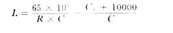
Calculate the maximum length of the cable. In the formula, R is the network resistance, the unit is Ω; C is the unit length issued capacitance, the unit is pF / m; Cf is the capacitance of the field device, the unit is pF, Cf = CN × 5000, CN is the field instrument parameter if the field instrument If there is no CN value, the CN is taken as 1. In engineering design, take the minimum of the two methods.
To connect the HART communication signal, the smart device requires it to have a level above 0.25VP-P, and the signal circuit of the two-wire smart device must have a resistance of at least 250Ω to communicate.
3 HART modulation and demodulation circuit design From the overall design program can be seen, HART modulation and demodulation circuit is an important aspect of the design. SART's HART communication chip HT2012 is used to design the modulation and demodulation circuit. The HT2021 is a monolithic CMOS low-power FSK modulation and demodulation chip. It follows the Bell202 communication standard and provides the physical layer of the HART protocol for process control instruments and other low-power devices. The HT2012 is powered by a single power supply of 3.5V or 5V, requires an external 460.8kHz clock, does not require external adjustment or bias, and is a half-duplex mode of operation. There are mainly four internal functional modules: clock module, demodulator module, and modulation Module and carrier detection module. HART modem by
 The control signal determines the working mode 0, send data by OTXA pin Is 1, the data is received by the IRXA pin.
 OCD is a carrier detection pin. When a valid carrier signal appears, the OCD pin is low, informing the CPU to read in demodulated data. It can be seen from the wiring method in Figure 3 that when the HART modem is working in the sending state, the chip still receives the carrier signal, and the OCD pin is still low, which should be noted when designing the program. The external must provide a clock signal of 460.8 kHz, which generates all internal and external timing. 19.2kHz is the chip output signal. The design circuit is shown in Figure 3.
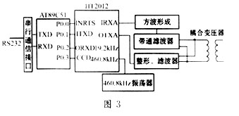
The design circuit is half-duplex. The FSK signal coupling method is transformer coupling, and other coupling methods can also be used. The input signal passes through a band-pass filter (bandwidth of 1200 Hz to 2200 Hz), and then is sent to the HT2012 through a square wave forming circuit. The output of HT2012 is a square wave signal, which is connected with a filter circuit to smooth the signal edge and filter out parasitic signals and harmonics. If the transmission medium can receive the square wave signal, the output filter can also be omitted. Both filters should have a constant phase delay over a wide range. The AT89C51 microcontroller interfaces with the HT2012 to generate HT2012 control signals and complete data input and output. AT89C51 single chip microcomputer completes the communication interface conversion task at the same time and interfaces with the microcomputer. In this design, the analysis and discrimination of the received data is done by the upper microcomputer.
After the hardware design is completed, programming is performed according to HART communication protocol application layer commands. Detailed specifications of HART commands are given in the relevant documentation of the HART communication protocol, including command format, data format, and response code format. Relevant materials can be found from the HART Communication Foundation website (http: ///.org).
4 Conclusion HART communication protocol is considered to be the de facto industry standard.
Simultaneous transmission of analog and digital signals brings greater flexibility to the monitoring system. Its shortcomings are mainly slower. Due to the large number of 4-20mA standard field devices, HART
Communication protocols still have a wide range of applications. In the context of this article's engineering application, a low-cost, high-precision measurement scheme is designed using the HART communication protocol. The design idea has universal significance and is suitable for monitoring tasks in other industrial sites.
references
2 Cai Jianxin, Lu Aiming. The principle and application of HART modem HT-2012. Electronic Technology Application, 1999 (5)
Guangzhou Ehang Electronic Co., Ltd. , https://www.ehangmobile.com