Basics of RF and microwave switch test systems
The tremendous growth of the wireless communication industry means that the testing of components and assemblies of wireless devices has ushered in an explosion, including the testing of various RF ICs and microwave monolithic integrated circuits that constitute the communication system. These tests usually require very high frequencies, generally in the GHz range. This article discusses key issues in RF and microwave switch test systems, including different switch types, RF switch card specifications, and issues that need to be considered in RF switch designs that help test engineers improve test throughput and reduce test costs.
The difference between RF switch and low frequency switch
It seems easy to convert a signal from one frequency point to another, but how to achieve extremely low signal loss? Designing switching systems for low-frequency and direct-current (DC) signals requires consideration of their unique parameters, including contact potential, settling time, bias current, and isolation characteristics.
High-frequency signals, similar to low-frequency signals, need to consider their unique parameters, which affect the signal performance during switching. These parameters include VSWR (voltage standing wave ratio), insertion loss, bandwidth, and channel isolation. In addition, hardware factors, such as termination, connector type, and relay type, can greatly affect these parameters.
The type of switch and the capacitance within the construction relay are common factors that limit the signal frequency of the switch. The material and physical characteristics of the relay determine its internal capacitance. For example, in RF and microwave switches over 40 GHz, special contact structures are used in electromechanical relays to obtain better performance. Figure 1 shows a typical configuration with a common termination between the two switch terminations. All signal connections are coaxial lines to ensure the best signal integrity (SI). In this case, the connector is an SMA female. For more complex switch structures, the common termination is radially surrounded by the individual switch terminations.
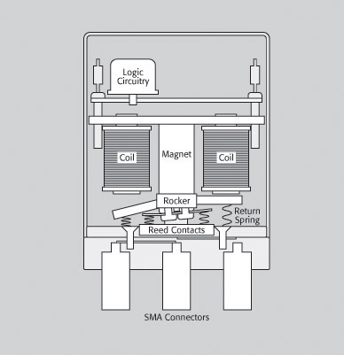
Figure 1-High frequency electromechanical relay
A series of complex switch topologies are adopted in RF switches. The matrix switch can realize the connection of each input and each output. There are two types of matrices used in microwave switch architectures-blocking and non-blocking architectures. A blocking matrix can connect any input and any output, so other inputs and outputs cannot be connected at the same time. This is an effective low-cost solution for applications that only need to switch to one signal frequency at a time, and the signal integrity is better, because there are fewer relay paths, and especially the problem of phase delay is avoided. The non-blocking matrix allows multiple paths to be connected at the same time. This architecture has more relays and cables, so it is more flexible, but the price is also higher.

Figure 2 – Single-channel blocking matrix and non-blocking matrix
Stacked switch architecture is an alternative form of multi-position switch. It uses multiple relays to connect one input to multiple outputs. The path length (which also determines the phase delay) is determined by the number of relays that the signal passes through.
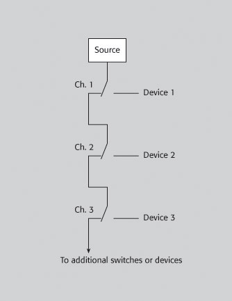
Figure 3-Stack switch architecture

Figure 4-Multiple switches (shown as a double switch)
The tree structure is an alternative to the cascading switch architecture. Compared with the cascading architecture, for the system with the same specification, the tree technology requires more relays, however, the isolation between the selected path and other unused paths will be better, which reduces the crosstalk. The tree structure has some advantages, including unterminated stubs, and the characteristics of each channel will be similar. However, having multiple relays on the selected path means greater losses and worrying signal integrity.
RF switch card architecture In the application of the RF switch card on the host of the test instrument, in order to ensure signal integrity, many electrical performance indicators need to be understood.
Crosstalk refers to capacitive coupling, inductive coupling or electromagnetic radiation generated between signals transmitted on different channels or between signals on the channels and output signals. It is generally described by a specific load impedance and a decibel number at a specific frequency.
Insertion loss is the attenuation of a signal when it is transmitted in a switch card or system, and is expressed in decibels for a specific frequency range. When the signal is low or the noise is large, the insertion loss is a very important technical indicator.
Voltage standing wave ratio (VSWR) is a measurement of the reflection of a signal on a transmission line and is defined as the ratio of the highest voltage amplitude to the lowest voltage amplitude of the standing wave on the signal path.
A limited frequency range in which signals are switched, transmitted, or amplified is called bandwidth. For a given load condition, the bandwidth range is defined by -3dB (half power) points.
Isolation is the voltage ratio of adjacent channels, defined as the decibel number over a frequency range.
RF switch design To design an RF switch system, a series of key factors need to be considered additionally.
Impedance matching-Assuming the switch is placed between the measuring instrument and the DUT (device under test), all impedances in several systems must be matched. For optimal signal transmission, the output impedance of the source should be equal to the characteristic impedance of the switch, the cable impedance, and the impedance of the DUT. In RF testing, the common impedance level is 50 or 75 ohms. Regardless of the impedance level required, proper impedance matching will ensure the integrity of the entire system.
The input VSWR and signal path determine the accuracy of the measurement.
Mismatch Uncertainty (dB) = 20 x log (1 +/- Γsig path * Γinst)
Where Γ = VSWR-1 / VSWR +1
If the signal path output and instrument input have a good VSWR, such as 1.3: 1, the mismatch uncertainty (Mismatch Uncertainty) is about +/- 0.15dB.
Termination-At high frequencies, all signals must be properly terminated, otherwise the electromagnetic waves will be reflected at the termination points, resulting in an increase in VSWR. A switch without termination will increase VSWR in the off state. A switch generally needs to provide a 50 ohm termination resistor to match the on or off state. After the VSWR is increased, if the reflection part is large enough, it may even damage the source end.
Power transmission-Another important consideration is the system's ability to deliver RF power from the instrument to the DUT. Due to insertion loss, the signal may need to be amplified. In some applications, it may be necessary to reduce the power of the signal to the DUT. The use of amplifiers or attenuators ensures that accurate signal power values ​​are transmitted to the switching system.
Signal filters-Signal filters are useful in some situations, such as when noise is accidentally added to the signal transmitted through the switch. If the original signal frequency is not suitable for the DUT test frequency, the filter is also useful. In this case, a filter can be added to the switch to change the signal bandwidth or filter out unwanted signal frequencies.
Phase distortion-As the size of the test system expands, signals from the same signal source may be transmitted to the DUT through different channels, resulting in phase distortion. This indicator is often referred to as transmission delay. For a given conductive medium, the delay is proportional to the signal path length. Different signal path lengths will cause the signal phase to shift, leading to erroneous measurement results. To reduce phase distortion, it is necessary to ensure that the signal path length is the same.
Summarize the discussion and understand the various design parameters in the purchase and construction of the RF / microwave switch system to help ensure the integrity of the signal and the system.
High Efficient Freight Elevator
Vertical Cargo Lift,Portable Elevator,Hydraulic Cargo Lift,Outdoor Freight Elevator
XI'AN TYPICAL ELEVATOR CO., LTD , https://www.chinaxiantypical.com