By designing an asynchronous structure FIFO in the MEMS signal processing circuit, the system can effectively reduce the frequent access to the MEMS. Design a FIFO with multiple working modes to meet some special attitude detection requirements and better meet the needs of intelligent operation of the system. A concrete and feasible solution is realized, which can be practically applied to various MEMS circuit modules.
MEMS sensors are new sensors manufactured using microelectronics and micromachining technology. At present, accelerometers have been widely used in smart terminals (such as smart phones), and gyroscopes will also be commonly applied to smart terminals in the next few years. At the same time, combined sensors, such as 3-axis accelerometers + 3-axis magnetometers, 3-axis accelerometers + 3-axis gyroscopes, and even 9-axis combinatorial sensors will be widely used in the future, and correspondingly, the amount of data processing will increase. Current data output rates for MEMS circuits such as accelerometers, gyroscopes, and magnetometers typically range from a few hertz to a few hundred hertz. The main system processing unit generally accesses the MEMS circuit through the serial communication interface I2C or SPI to acquire data. In addition to some data that needs real-time response, the main system unit may sometimes not want to frequently use the serial interface to detect the MEMS circuit state, see the internal Whether the data is ready and then read the valid data, because this will reduce the efficiency of the entire system. For smart terminals like smartphones, as the functions become more powerful and the system handles more and more tasks, how to balance will be a problem.
In view of the above situation, this paper designs a 48-bit data width, 64-level memory depth asynchronous FIFO (First In First Out), which can effectively solve the problem of frequent access to the MEMS circuit by the main system unit. The FIFO has four working modes: bypass mode, continuous mode, first-in first-out mode and interrupt mode. In the interrupt mode, by setting different conditions, it is possible to automatically capture some special states without the intervention of the main system unit. The data. This can save a lot of system resources.
1 FIFO system design
The traditional asynchronous FIFO [1-2] uses the trigger synchronous asynchronous input signal to reduce the probability of occurrence of metastability, and then the address is eliminated by the Gray code coding method to eliminate the empty state misjudgment caused by the multi-bit change of the address, which needs to be used. Dual port RAM. Although the use of trigger synchronization can reduce the probability of metastability, it also brings the difficulties of timing analysis and post-synthesis simulation. Gray code brings the complexity of the design. It can be designed by sequential logic to insert a clock tree during layout and routing to avoid the incomplete state of the empty state. At the same time, true dual-port RAM is not supported by every integrated circuit line. The use of pseudo-portal RAM is more practical and can be applied to a wider range of applications.
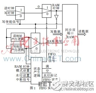
The entire system implementation also includes I2C and SPI interface modules, signal processing modules, and interrupt detection modules. This article only describes the FIFO modules. The block diagram of the implementation of the FIFO module is shown in Figure 1. The write clock is the MEMS data sampling clock, and the read clock is the serial I2C or SPI read data clock. In order to eliminate the conflicts that occur while reading and writing, a write enable signal is added, which is generated by the internal logic at the same time as the write clock, and the write clock has a higher priority than the read clock. This may introduce a problem, that is, when reading and writing happens at the same time, the data read is still the previous data, but can be set to the first-in first-out mode, and the data is not updated after the data is full, so there will be no such problem. . Mode settings and watermark threshold settings are written via the serial port I2C or SPI. Synchronous dual-port RAM uses the SMIC 0.18 m Process Memory Compiler to synthesize the 64&TImes; 48-bit IP module, which is a pseudo dual-port RAM with read and write clocks shared. The 48-bit data width can simultaneously store MEMS detection data of 3 axes, and the 16-bit data width of each axis can basically meet the current MEMS precision requirements.
2 functional module design
2.1 Read Address Generation Logic
The read address generation logic generates a read address pointer based on the operating mode and the state of the FIFO. If the read clock is valid and the FIFO is not empty, the read address is incremented by one. If the FIFO is empty, the read address remains unchanged. In the continuous working mode, since the data is continuously scrolled and updated, if the data is full, if the write is valid, the read address is incremented by 1, ensuring that the read address pointer points to the first written data address.
2.2 Write Address Generation Logic
If the write is valid, the write address pointer is automatically incremented by one. By controlling the RAM clock, in the first-in first-out mode, if the FIFO is full, writing new data to RAM is terminated, so the write address pointer is no longer updated unless the entire FIFO module is re-enabled.
2.3 State Generation Logic
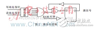
The state of the FIFO can be obtained by directly subtracting the read address pointer from the write address pointer, but it is also necessary to consider that when the FIFO is full, the read address pointer and the write address pointer point to the same address, and the data is 0 when the data is subtracted. It is. Therefore, it is necessary to increase the intermediate register, output the value of the subtractor when it is not full, and output the full value of 1 when it is full. The full and empty status signals, the watermark flag signal and the FIFO stop signal are all generated by the timing logic. The full signal logic circuit diagram is shown in Figure 2, which is triggered by the inverted signal of the RAM clock. The watermark can be obtained by setting a threshold of the watermark, and the threshold can range from 0 to 63. When the status value of the FIFO exceeds the set threshold, a watermark flag interrupt is generated; when the state of the FIFO is less than the set threshold, the watermark flag interrupt is cleared, which allows the host system to flexibly select according to the application. There are two cases of FIFO stop signal. In the first-in first-out mode, the FIFO stop signal is generated after the full-time, the RAM data stops updating. In the interrupt mode, the FIFO stop signal is not generated before the interrupt signal is generated. After the interrupt signal is generated, A FIFO stop signal is generated based on the full state signal.
3 working mode
3.1 Bypass mode
In the bypass mode, the reset signal is valid, the FIFO does not work, and the main system unit directly reads out the data output by the ADC.
3.2 continuous mode
In continuous mode, the data is continuously updated in the FIFO. Accordingly, the read address pointer and the write address pointer are also continuously updated, and the read address pointer points to the first input RAM address. In continuous mode, if the write clock is valid after the data is full, the read address pointer and the write address pointer need to be incremented by one because the first data has already been overwritten. At the same time, when the write clock is invalid, the read clock is valid, and the read address pointer is also incremented by one.
3.3 first in first out mode
In the first-in first-out mode, the data is automatically terminated when the data is filled, and a full interrupt signal is generated. In the absence of a read clock, the final read address pointer and write address pointer will point to address 0 at the same time. Accordingly, in the case of not being full, if the read clock is valid, the final read address pointer and the write address pointer will simultaneously point to one of the intermediate addresses.
3.4 Interrupt mode
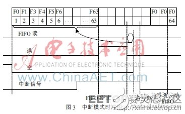
In the interrupt mode, the data first works in continuous mode. If the interrupt signal is valid, it enters the first-in first-out mode, and the data is automatically terminated when the data is filled. The working sequence diagram is shown in Figure 3. When the data is not full, an interrupt signal is generated. When the data is full, a termination signal is generated. The full interrupt signal is set to 1. After the data starts to be read, the full interrupt signal is cleared. After the data is completely read, the null interrupt signal is set. If the FIFO needs to repeat the above workflow, it is necessary to clear the interrupt and restart the FIFO. When the data starts to be rewritten into the FIFO, the null interrupt signal is cleared.
Different from the traditional asynchronous FIFO, this paper implements a simpler and practical FIFO structure, which is flexible and reliable. By adding an asynchronous FIFO design to the MEMS signal processing circuit, the system's need for low power consumption and operational flexibility can be better met. Through DC integrated parallel chip verification, the FIFO circuit has been applied to a variety of MEMS circuit products, and has achieved good results. Especially for future MEMS combined sensors, increased data volume and special gesture processing, the introduction of more flexible FIFO will bring more advantages.
In many electronic communication equipment and instruments where always use some cable assemblies to connect some electronic units and circuits. Xi'an KNT Scien-tech can use their technology, euqipment, skilled operation, advanced test equipment and method (IEC 9661-4). different connnectors (SMA, SMB, N, TNC, etc. ) and different cables (FLExible cable, semi-flexible cable, Semi-rigid cable, corrugated cable etc.) to offer customer various reasonable price cable assemblies fully with the customer requirements.
SMA cable
Xi'an KNT Scien-tech Co., Ltd , https://www.honorconnector.com