One of the great advantages of metal panel capacitor (MoC) touch systems is the flexibility of their sensors. That is to say, its sensor design can be as many as hundreds, and the same look and feel can be achieved through various deployment methods.
Faced with so many dazzling potentials, it is difficult for designers to focus on a specific design unless they are familiar with the different design options and the pros and cons of each. Therefore, we recommend that you consult a mechanical engineer because they know more about the materials available, the characteristics of the materials, and the manufacturing process.
We can build a MoC touch system based on Microchip's mTouch® capacitive sensors and associated electronics and software. The MoC design differs in that the user's finger is replaced by a conductive target layer suspended above the capacitive touch sensor with a thin spacer layer in between. When the user presses the target layer, the target layer is slightly deformed - no more than 10 μm - to be closer to the sensor, and this change in spacing causes a detectable change in the sensor capacitance. The capacitive touch interface (electronic components and software) will detect changes in capacitance and report this press to the system.
This means that the sensor is electrically isolated from the environment, thus improving noise, proximity and crosstalk issues. The grounded target layer provides a non-destructive path for ESD (electrostatic discharge) energy. At the same time, the isolation of the sensor from the environment also eliminates the problem associated with water. Because the sensor's drive requires physical force, it is suitable for Braille applications and gloved users. The use of metal panels gives the final product a more professional look and feel.
Sensor system construction
To build a MoC sensor system, we need a standard capacitive sensor, a spacer layer that opens above the sensor, and a conductive panel and target layer. Figure 1 shows a typical sensor stack structure. In this configuration, the conductive target layer acts as the other plate of the capacitive sensor and has the required elastic bending capability so that the panel can be restored to its original state after the force is removed.
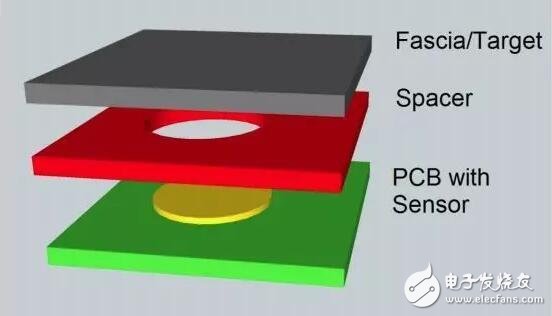
Figure 1: Typical metal panel capacitive sensor stack structure (single layer)
The panel is on the top surface of the laminate structure with markings and button legends. The electrically conductive target layer acts as another conductive surface of the sensing capacitor. Together, the two provide the user with relevant information, constitute another grounding layer of the sensing capacitor, and realize the mechanical elasticity of the button.
There are a number of factors to consider when selecting panels and target layer materials, including how much drive force is required to press a button, the appearance of the panel to be favored, environmental factors, whether the button requires backlighting, and whether the panel and target layer require backlighting. In general, we'd better combine the design of the panel and the target layer, as they often need to work closely together to get up and running.
The simplest implementation is to use a single metal layer to act as both the panel and the target layer. That is, the mark on the metal target layer can be regarded as a panel layer, or the printed film adhered to the target layer can be used as a panel layer. This single metal layer provides all the mechanical resilience needed for the button and sensing capacitor (target layer) and the other ground plate. Figure 1 shows an example of a typical single-layer metal laminate structure.
The driving force is determined by the thickness of the metal used for the panel and the target layer, the size of the button, the elasticity of the metal used, and the relationship between the panel and any backside etching of the target layer. In most cases, the size of the buttons and the thickness of the material are the main factors.
The elasticity of the metal in the panel and the target layer is an important factor in determining the driving force of the button. For example, stainless steel is a flexible metal, but its elasticity is not comparable to that of aviation grade aluminum. On the other hand, aluminum has a lower yield strength and is more prone to dents and indentations when subjected to high driving forces. Therefore, the choice of materials requires a balance between ensuring sufficient flexibility in the case of low driving forces and a high yield strength to ensure damage when subjected to high driving forces.
In terms of appearance, modern screen printing and coating processes can create foils that create realistic textures from granite to wood. We can plate all or selectively metal surfaces of metal panels by electroplating to create relevant markings and create a specific look. Anodized aluminum can even print photo-quality images.
Two major environmental concerns are wear resistance and chemical resistance, including water. Stainless steel can withstand most common chemical cleaners, including water, and has good wear resistance. On the other hand, ordinary steels are prone to rust and chemical discoloration, and their wear resistance is only moderate. The aluminum material treated by the anodized coating has good wear resistance, but the anodized layer is porous and needs to be sealed with a polymer coating, otherwise it is easy to rust.
Many designers tend to avoid using metal panels because they mistakenly believe that metal panels do not provide backlighting. In reality, however, this is achievable, but only slightly higher than the cost of polymer panels. In general, we can selectively implement metal perforations and achieve backlighting by means of a polymer backfill seal to block dust and moisture.
Plastic panel with metal cover
The use of a plastic panel layer and a metal cover sheet made by screen printing or vapor deposition as the target layer is the second most simple implementation. This method, like the design of a single metal layer, marks the surface of the plastic panel and provides the flexibility required for the keys from the plastic panel. The metal cover slip at the bottom of the plastic layer acts as the other ground plate for the sensing capacitor. Referring to the laminated structure of Fig. 2 .
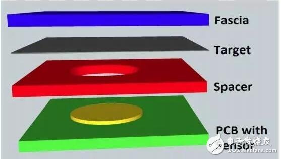
Figure 2: Example of a plastic sensor stack structure
In this design, the driving force is determined by the relationship between the size of the button and any back etching, but depends on the thickness and elasticity of the plastic used. The smaller the button and the thicker the material, the greater the driving force. However, despite the relatively high hardness of stainless steel and aluminum, the elasticity of plastic is far superior to that of metal. In this way, thicker panels and target layers can be used while maintaining the same driving force. At the same time, it is also more resistant to high bending angles, and relatively less likely to cause dents and permanent deformation.
Like sheet metal, modern screen printing and coating processes also allow plastic sheets to present any type of surface desired by the designer. The surface of the plastic substrate can also be completely or selectively used to create a glossy appearance and marking by using a metal coating.
One difference in the use of plastic is that there is a potential problem of maintaining optical transparency at higher thicknesses. Polyester materials can create transparency problems, but this is usually not a problem in the typical thickness range used for sensor design. Both polycarbonate and polyethylene have good optical clarity. Some adhesives also have good optical clarity. Designers should ensure that a suitable combination of plastic and adhesive is selected to avoid a cloudy or hazy appearance.
Although water is no longer a major problem in plastic panel design, the issue of wear resistance and chemical resistance is even more pronounced. Another potential problem associated with the environment is the dimensional stability of the material as a function of temperature. If there is a significant difference between the rate of expansion of the panel material and the rate of expansion of the material to which it is bonded, the adhesive will lose its effect, resulting in false triggering, variable sensitivity, and significant crosstalk problems between the sensors.
One of the environmental concerns of the food preparation and medical market is the microbial contamination tolerance of the material. Polyester and polycarbonate materials are available in antimicrobial coatings and are therefore the material of choice for these two markets.
Anti-fogging and UV-resistant yellowing are also desirable if the sensor will also be exposed to direct sunlight.
Transparent and translucent plastics are the materials that make it the easiest to implement. Plastics not only transmit light, but also provide longitudinal light transmission, so the backlight of the entire design surface can be achieved with side-lit LEDs. If metal surface plating is employed, the pinhole openings can be implemented with a simple etching process to achieve similar effects to the more costly backlight selections mentioned for solid metal layers.
Metal plastic common mode design
The third option is to use a combination of plastic and metal to make a single-layer panel and target layer. By etching or stamping the metal layer, a certain amount of space is left around the switch. These voids are then filled with plastic by an injection molding process. One of the great advantages of using both metal and plastic is that it combines the strengths of both. This design has the wear resistance of metal, plastic transparent and translucent characteristics, and the driving force will be harder than using plastic alone, and softer than using metal completely. In fact, we can adjust the driving force by changing the ratio of plastic to metal associated with bending each button. Figure 3 is an example of a co-molded panel and a target 5 layer. The light gray material is aluminum, while the dark gray is the injection molded plastic around the sensor.
Figure 3: Metal and plastic common mode panels and target layers
In common mode design, the driving force is also determined by the same factors, just like the design of metal or plastic alone. The difference is that the actual force will be determined by the weighted average of the two material properties. The driving force of this design will be between the two values ​​of pure plastic design and pure metal design. Unfortunately, the exact calculation of the driving force depends to a large extent on the geometry of the sensor used. We can average the values ​​under pure metal conditions and pure plastic conditions to get a useful approximation. First, we calculate the driving force of two similar buttons, one made of plastic and the other made of metal. Then calculate how much plastic and how much metal is used around the button, and calculate the two driving force values ​​according to the proportion of the two materials around the button. Taking the average of the two results gives a rough estimate of the driving force required for the common mode design. The required driving force can be adjusted by changing the ratio of metal to plastic used, or it can be fine-tuned by adjusting the button stroke threshold in software.
The appearance of the sensor is the reason why this implementation is widely favored. Metal provides good wear resistance, while plastic creates the visual profile of the sensor and is responsible for backlighting the sensor. Use the same techniques as described above to create the look and feel that designers need with modern screen printing and coating processes.
The effects of wear resistance and chemical resistance are also more complicated in composite design. It is necessary not only to select metals and plastics suitable for the pre-stage 6 environment, but also to consider the compatibility and adhesion of the plastics relative to the metal. For example, if the coefficient of expansion of the metal is higher than that of the plastic, then in extreme low temperatures or extreme high temperatures, the metal edges may be detached from the plastic causing dust and moisture to sneak into the sensor device. If the expansion coefficient of the plastic is higher, the plastic may generate pressure and cause metal deformation under higher temperature conditions, which may cause false pressing.
In terms of backlighting, plastic provides a way to pass light through the metal, both to illuminate the button functions and to make the button outline more visible and user-friendly. Unfortunately, the use of plastics in design is often isolated, so individual locations may require separate illumination.
in conclusion
With these different sensor design techniques, designers have a great deal of flexibility when creating novel user interfaces. By combining different materials, configurations and techniques, you can create a truly unique range of controls from both an aesthetic and ergonomic point of view. However, these techniques are not exhaustive. Designers should break through traditional thinking patterns and communicate with third-party creative design service providers to gain more design ideas.
As mentioned earlier, equalization techniques are a major determinant of the distance that a CoaXPress cable can achieve when maintaining a given data rate. To optimize this parameter, Microchip Technology's 600 MBps CoaXPress chipset uses a dedicated adaptive equalization algorithm to overcome digital signal degradation due to cable attenuation. The equalizer estimates the frequency dependent loss caused by the cable and compensates accordingly
1.0mm (.039″) Pitch Pin Headers
Overview
Antenk offers a variety of high quality and competitively priced 1.0mm pitch single, dual, three, quad row pin (male) headers used in many board-to-board PCB connections, fitting small-sized, densely-packed devices.
This low-profile component is made from high-temperature thermoplastic and is offered with several means of connections and mounting styles such as through-hole (THM) or surface mount (SMT) and can be in vertical (straight), elevated or at a right angle configuration/orientation dissipating current of about 1.0 A or less.
The pin (male) header is generally mated with receptacle or stackable header connectors (female sockets). This types of pin headers are suitable for PCB board to board connection or for signal transmission application.
Applications of 1.0mm Pitch Pin Headers
Its small size is most suitable for PCB connections of small equipment and devices such as WiFi equipment, gaming consoles, measurement instruments, and other equipment in need of a special interface to become interconnected
Mount Type: Through-hole vs Surface Mount
At one side of this pin header is a series of pins which can either be mounted and soldered directly onto the surface of the PCB (SMT) or placed into drilled holes on the PCB (THM).
Through-Hole (Poke-In)
Best used for high-reliability products that require stronger connections between layers.
Aerospace and military products are most likely to require this type of mounting as these products experience extreme accelerations, collisions, or high temperatures.
Useful in test and prototyping applications that sometimes require manual adjustments and replacements.
1.0mm vertical single row header, 1.0mm vertical dual row header, 1.0mm Elevated single row pin header, 1.0mm Elevated dual row pin Header, 1.0mm Right-angle single row header and 1.0mm Right-angle dual row header are some examples of Antenk products with through-hole mount type.
Surface-Mount
The most common electronic hardware requirements are SMT.
Essential in PCB design and manufacturing, having improved the quality and performance of PCBs overall.
Cost of processing and handling is reduced.
SMT components can be mounted on both side of the board.
Ability to fit a high number of small components on a PCB has allowed for much denser, higher performing, and smaller PCBs.
1.0mm Right-angle Dual Row pin header, 1.0mm SMT Single row pin header, 1.0mm SMT Dual row pin header and 1.0mm Elevated Dual Row Pin Header are Antenk`s SMT pin headers.
Soldering Temperature for 1.0mm Pitch Pin Headers
Soldering SMT pin header can be done at a maximum peak temperature of 260°C for maximum 60 seconds.
Pin-Type: Vertical (Straight) and Right-Angle
1.0mm pitch headers may be further classified into pin orientation as well, such as vertical or straight male header or right-angle male header.
Vertical or Straight Pin (Male) Header Orientation
One side of the series of pins is connected to PCB board in which the pins can be at a right-angle to the PCB surface (usually called "straight" or [vertical") or.
Right-Angle Pin (Male) Header Orientation
Parallel to the board's surface (referred to as "right-angle" pins).
Each of these pin-types have different applications that fit with their specific configuration.
PCB Connector Stacking
Elevated Pin Header Orientation
Elevated pins aka Stacked Pins or Mezzanine are simply stacked pin headers providing an exact distance requirement between PCBs that optimizes electrical reliability and performance between PCB boards.
Profile Above PCB
This type of configuration is the most common way of connecting board-to-board by a connector. First, the stacking height is calculated from one board to another and measured from the printed circuit board face to its highest insulator point above the PCB.
Single, Dual or Multiple Number of Rows
For a 1.0mm straight or vertical male pin header, the standard number of rows that Antenk offers ranges from 1 to 2 rows. However, customization can be available if 3 ,4 or n number of rows is needed by the customer. Also, the number of contacts for the single row is about 2-50 pins while for dual row, the number contacts may vary from 4-100 pins.
Pin Material
The pins of the connector have been designed with copper alloy. With customer`s demand the pins can be made gold plated.
Breakaway design
The pin headers are also equipped with a breakaway design making them fully compatible with their female receptacles.
Custom 1.0mm Pitch Pin Headers
Customizable 1.0 mm pitch pin headers are also available, making your manufacturing process way faster as the pins are already inserted in the headers, insulator height is made at the right size and the accurate pin length you require is followed.
Parts are made using semi-automated manufacturing processes that ensure both precision and delicacy in handling the headers before packaging on tape and reel.
The tape and reel carrier strip ensures that the headers are packaged within accurately sized cavities for its height, width and depth, securing the headers from the environment and maintaining consistent position during transportation.
Antenk also offer a range of custom Tape and reel carrier strip packaging cavities.
Male Header Pins,1.0Mm Male Header,1.0Mm Pin Header,1.0Mm Male Header Pins, 1.0mm THM Male Header, 1.0mm SMT Male Header
ShenZhen Antenk Electronics Co,Ltd , https://www.pcbsocket.com