The airport navigation station is the resettlement point of the aircraft navigation device. It is very important that once the failure occurs, it will not only affect the normal navigation of the aircraft, but even cause more serious consequences. A large part of the failure of navigation equipment is caused by a power system failure or a destructive change in the indoor environment of the navigation station. Therefore, the establishment of a centralized monitoring system is conducive to managers to understand the operating status and environmental conditions of navigation devices in a timely manner, and to improve the safety of aircraft navigation and the efficiency of equipment maintenance and management. However, at present, there are still various shortcomings and defects in the navigation station monitoring system of some airports. For example, video surveillance and environmental data collection are independent of each other, resulting in repeated laying of monitoring communication links, reducing resource utilization; less monitoring types, some monitoring only power data and temperature and humidity data, without leakage, smoke, infrared, etc. The monitoring is not conducive to the comprehensive analysis of the monitoring data to provide reliable monitoring information; some small airports have navigation stations installed wall-mounted air conditioners instead of precision air conditioners, wall-mounted air conditioners do not have RS485 communication interfaces, resulting in failure to pass the monitoring system Control can only be manually adjusted manually; the compatibility and scalability of the system equipment is poor, and only the equipment of the fixed manufacturer can be updated. The new type of monitoring equipment or the monitoring equipment of different manufacturers cannot be successfully accessed, which is not conducive to the system upgrade. Although some configuration software can be smoothly accessed, the price is high and the construction cost is too high. In view of the above shortcomings and shortcomings, this paper designs a comprehensive centralized monitoring system with good scalability, compatibility, high efficiency, reliability and high resource utilization.
1 The overall design idea of the acquisition device hardware The system mainly divides the monitoring data into two parts: audio and video data and environmental data. The audio and video data is collected by the camera and microphone and compressed by the video motherboard into MPEG4 video format. The environmental data is collected by environmental data. The card is collected, and the video motherboard uses the transparent transmission method to forward the data of the environmental data acquisition card directly to the TCP port specified by the upper layer software; the bottom layer environment collection device generally selects the RS485 data interface, and can directly access the environment data acquisition card to work, so that Greatly improve the compatibility and scalability of hardware devices. The environment capture card can be connected to the video compression motherboard at any time in a ready-to-use manner. Therefore, where the environment data needs to be collected, the environment capture card should be connected to the video compression motherboard, otherwise no access is required.
The hardware interface and communication protocol are compatible with the interface and communication protocol of the original monitoring system of the airport navigation station, and protect the original investment of the user. For the transmission of data, the audio and video data and the environment collection data are uniformly packaged, and the microwave is directionally transmitted to the navigation and monitoring center, and the upper layer centralized monitoring software performs data processing uniformly, thereby saving communication link resources; centralized monitoring software at the upper layer With the supporting data communication, automatic alarm reception, video real-time playback, alarm data maintenance and other software, Zhongxuan can realize the functions of rapid, accurate, accurate positioning and statistical analysis of alarms, providing scientific navigation safety for airports. The basis for decision-making is to enhance the rapid response capability and command capability of airport personnel.
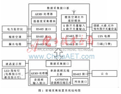
The system structure design of the front-end acquisition device is shown in Figure 1. It is mainly divided into video compression motherboard and environmental data acquisition interface board. The video compression motherboard is mainly responsible for compressing the video signal from the CCD camera and the sound of the microphone into an audio and video stream of MPEG4, and acquiring various environmental data from the data acquisition interface board at regular intervals. The data acquisition interface board mainly stores various environmental data detection devices based on RS485 and I/O communication, and the processed audio and video data and the environment detection data are uniformly packaged into Ethernet data packets and transmitted through the network interface, and the network interface An RJ45 connector is provided and can be transmitted to the navigation monitoring center by microwave transmission. The centralized management software of the monitoring center is responsible for receiving and processing audio and video data and environmental data. The video data can be decoded and displayed in real time. The environmental data can be compared with the set parameters to determine whether it is normal and whether an alarm is required.
This article refers to the address: http://

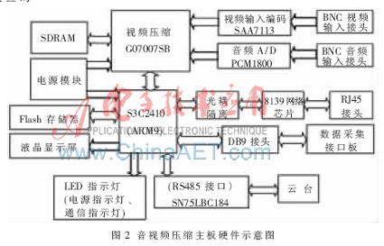
2 video compression motherboard design audio and video compression motherboard shown in Figure 2, using GO7007SB chip for audio and video compression. This chip is a multi-format MPEG4 video encoding chip from WIS Corporation of the United States. It uses a variety of high-precision compression algorithms, can output MPEG4, MPEG-2, MPEG-1, H.263, MJPEG and other data stream formats, while supporting perfect audio and video synchronization output. The maximum specifications that can be output are: the resolution of the NTSC system is 720×480 at a frame rate of 30 S/s, and the resolution of the PAL system at a frame rate of 25 S/s is 720×576. In addition, the chip also provides a rich peripheral hardware interface: support 10-bit RGB Bayer video decoder interface, 32-bit data, 100 MHz SDRAM data bus interface, I2C bus interface, I 2 S external audio / PCM encoder / DSP interface And flexible HPI host interface; can support multiple types of CPU, most CMOS and CCD sensors and Philips SAA711X video processor can be seamlessly connected to the video input interface.

The video capture was done by the video data capture chip SAA7113 from Philips. The SAA7113 mainly digitally samples and converts the analog video signal into a digital video signal of the ITU656 standard output format. The video signal input at the front end can be NTSC, PAL or SECAM. The SAA7113 can input the captured ITU656 YUV 4:2:2 format digital video data to the G07007SB through the 10-bit RGB Bayer video decoder interface under the control of the G07007SB's I2C bus timing.
Audio acquisition is done by the stereo audio acquisition chip PCM1800 produced by TI's BURR-BROWN company. It mainly converts the analog stereo audio signal into a digital audio signal conforming to the I2S bus standard format, and the digital audio signal is input from the I 2 S external audio interface to the G07007SB. The G07007SB supports ADPCM encoding, allowing 1:4 audio compression to produce audio sample counts and audio labels for A/V sync.
The central controller of the motherboard uses Samsung's S3C2410 embedded processor. It is a SoC chip based on ARM940 core, which mainly controls and manages the whole system, such as system level initialization, configuration, user interface, user command execution, PC communication and system control. The S3C2410 is embedded in the source code and the Clinux embedded operating system is the control platform. The S3C2410 and GO7007SB communicate via HPI. The HPI physically connects the GO7007SB port to the ARM bus controller BUSC. The S3C2410 opens a 32 KB window in the GO7007SB memory map by programming the HPI, and then accesses the GO7007SB memory. In this way, both the S3C2410 and GO7007SB can access the SDRAM, effectively sharing a large number of image data blocks. The S3C2410 and GO7007SB share a data structure for command request, acknowledgment, and data interaction.
The ARM9 processor can also directly connect with the data acquisition interface block to read the data of the environmental monitoring device. After processing, it is packaged with the audio and video data and sent to the upper layer monitoring system of the remote centralized monitoring center via the 8139. The flash memory is used to permanently save the network parameters and configuration parameters of the device. When the power is reset, the motherboard is read out. The LCD screen is used to display the time and indoor temperature and humidity of the site as well as the current state of the device. If there is a fault, the ALARM message will be displayed. Normally, the time and temperature and humidity data will be refreshed every 1 s.
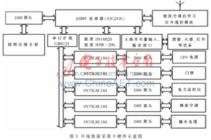
3 Environmental data acquisition card design environment data acquisition card shown in Figure 3. The environmental data acquisition card can communicate with the audio and video compression motherboard through the DB9 connector to provide the collected environmental data. The capture card embeds the Linux operating system on the ARM9 processor S3C2410 as a control platform to control communication with external environmental data acquisition devices. In addition, the GM8125 expands a serial port into 5 serial ports, and then converts RS232 signals into RS485 signals through 5 SN75LBC184 chips. Since most of the devices for environmental acquisition are RS485 interface signals, the extended 5 RS485 interfaces can be connected to any. 485 acquisition equipment. This greatly increases the load capacity and scalability of the system.

The temperature and humidity acquisition module is mainly composed of temperature and humidity sensors. The temperature sensor adopts the intelligent temperature sensor DSl8B20 produced by DALLAS Semiconductor Company. The collected data can be directly sent to the microprocessor without A/D conversion, and the measured temperature can be directly read out. It requires only one interface line for bidirectional communication with the ARM9 processor; the DSl8B20 is powered by a data line with a temperature measurement range of -50 °C to +125 °C. The 9~12 digit digital value reading mode can be realized by programming, and the measurement accuracy is ±0.5 °C. The humidity sensor adopts HSM-20G. The principle is that the value added by each change of 0.03 V humidity is 1%, and the output voltage value needs to be converted into digital quantity by ADC0809 for the single chip processing, so that the digital tube displays the humidity value. The operating voltage range is 5.0±0.2 V DC voltage and the test accuracy is ±5% RH. The working current (maximum) is 2 mA, the storage environment humidity ranges from 0 to 99% RH, and the working environment humidity ranges from 10% to 90% (instantaneously up to 100% RH).
The digital input and output interface is mainly composed of 16 optocouplers and 8 relays. The optocoupler is used to isolate the impact of the transient high voltage current to protect the acquisition board; the eight relays are designed to drive the switching output signal with a large current. The digital input signal comes from devices such as smoke, fire and infrared detection. The digital output signal can support the power cut-off, turn on or off the power supply of a device or the switch of the drive indicator.
The infrared remote control module of the wall-mounted air conditioner is mainly composed of a pair of infrared transceiver chips, a single-chip microcomputer and a flash memory chip, and the remote control command for cooling or heating that needs to be set is received by the infrared receiving chip and stored in the flash, so that the completion is completed. Instructional reading of wall-mounted air conditioners. The upper management software can send instructions to the wall-mounted air conditioner infrared remote control module in the navigation station monitoring center, and the single-chip computer extracts the remote control code stored in the flash corresponding to the instruction, and is transmitted by the infrared transmitting chip, as long as the infrared emitting head is aligned with the wall-mounted air conditioner. Complete the remote control.
4 Environment data acquisition network protocol packet video compression motherboard uploads the compressed video stream to the monitoring center management software for real-time playback through the TCP port, and the environment acquisition board is also configured according to what type of device is attached to each sub-serial port. The configuration information is downloaded from the upper management software. The device on each sub-serial port is polled at regular intervals, and the data packet returned by the device (with standard MODBUS protocol or other custom RS485 protocol) is uniformly encapsulated into the data payload from another TCP. The port is uploaded to the upper layer software (the video stream and the environment data each occupy a TCP port, which facilitates protocol parsing and processing).
The environmental data network packet format is shown in Figure 4. When the upper layer software receives a packet of complete data, the 16-bit synchronization word is removed, and the 8-bit packet length is obtained. The data from the packet length to the CRC belongs to the CRC check field; the CRC-16 check is performed first. If the data is correct, the serial port number, response flag and payload data are extracted. The payload data is the Modbus or RS485 protocol package of the complete underlying environmental monitoring device. The upper management software records the device connected to a serial port of the capture card in the database, so the device type and protocol packet structure can be determined by executing a database query with the command code and the serial port number as parameters; if it is connected under a serial port number After entering multiple RS485 devices, you need to continue to parse the payload data, match the device type and device address, and the different device addresses on a RS485 bus are different. If the response flag in the protocol is 1, the data packet sent to the upper layer software must be replied to whether it is successfully received, in order to continue to send the next data packet, otherwise it will be resent continuously to ensure that the data is uploaded accurately.

The instructions sent by the upper layer software also adopt the protocol packet format. After determining the serial port of the capture card connected to the device, the 485 data of the device is encapsulated into the payload field, and other fields are calculated and filled, and then the video compression is performed. The main board is transparently transmitted to the acquisition card. The acquisition card can extract the load data according to the command code and the serial port number and directly forward it to the 485 bus.
The device is designed to meet the many shortcomings and defects in the centralized monitoring of the indoor environment of the airport navigation station, and has designed more monitoring interfaces, which are compatible with more underlying monitoring devices, integrating video monitoring and indoor environmental monitoring data collection functions. The output is Ethernet data. It has good scalability, compatibility and reliability. It is not only suitable for monitoring of airport navigation stations, but also suitable for other monitoring environments, and has good promotion and application value.
references
[1] WIS Technologies. GO7007SB MPEG Encoder Datasheet. 2003.
[2] Philips Semiconductors. SAA7113H 9-bit Video Input Processor. 1999.
[3] Burr-Brown. PCM1800 Datasheet.1997.
[4] Gao Jianhua, Wang Shu. Embedded Audio System Design Based on S3C2410 Microprocessor and UDA1341 Stereo Audio Codec[J]. Foreign Electronic Components, 2006(6): 35-37.
[5] Ma Wenhui, Li Lanyou. Serial Communication in Linux Environment [J]. Instrumentation Users, 2005, 12(1): 39-41.
[6] Li Changming. Software Development Process Based on ARM and Linux Embedded System[J]. Industrial Control Computer, 2006, 19(3): 47-48.
Wifi Control Vacuum Cleaner,Thinnest Robot Vacuum Cleaner ,Air Purifier Wifi Control,Low Noise Cleaner Robot
NingBo CaiNiao Intelligent Technology Co., LTD , http://www.intelligentnewbot.com