Method for analyzing power flow fault of unbalanced distribution network with multiple PV nodes
According to the characteristics of radial, weak ring and three-phase unbalance of distribution network, this paper combines multi-port hybrid compensation technology to realize the unification of three-phase tidal current and non-ground fault calculation based on the previous generation pushback. . The ground fault is treated separately, thus avoiding the calculation non-convergence caused by the grounding point voltage being zero in the general calculation of the general power flow and the fault. At the same time, for the case of one or more PV nodes in the distribution network, a method for compensating the PV nodes is proposed.
Keywords: distribution network; compensation technology; PV node
An Approach for Power Flow Analysis and Fault Analysis of Asymmetrical DistribuTIon System with MulTI-PV Node
PENG Shu-tao, LIAO Pei-jin, LI Lin, WANG Guang-ming
(Department of Electrical Engineering, Xi'an Jiaotong University,
Xi'an, 710049)
Abstract: This paper shows a uniform approach for three-phase power flow and un-grounding fault. Based on forward and backward sweep method and distribuTIon system specialTIes, the approach makes use of multi-port compensation technology. In order to avoid divergence in the Common uniform approach because of grounding fault, grounding fault is dealt with other method. This paper also presents a compensation method for PV node.
Key word: distribution system;compensation technology;PV node
0 Introduction Power flow fault calculation is a basic calculation of the power grid. The reliable power flow fault calculation method must be accurate, stable and practical. For the distribution network, due to its own characteristics, such as the general operation in the form of radial or weak ring network, the three-phase load and electrical parameters are unbalanced, and the branch parameters R and X are not much different. . Therefore, it also puts special requirements on the calculation method of the power flow fault of the distribution network. Firstly, the convergence problem is highly valued in the power flow calculation of the distribution network. For example, because the ratio of the branch parameters R to X is relatively large, the algorithms that are effective in the transmission network, such as the fast decoupling method, are not in the distribution network. Effective again. Secondly, in the fault calculation, due to the existence of three-phase asymmetric components and loads, the calculation of the power flow fault cannot use the one-phase calculation method, and the three-phase power flow fault calculation must be performed. In the calculation of three-phase power flow faults, it can be divided into phase component method and sequence component method according to the way of processing three phases. However, due to the characteristics of the distribution network itself, the application of the phase component method in the calculation of tidal current faults in unbalanced distribution systems is better [1, 2].
At present, the calculation of power flow faults for distribution networks is mainly based on the previous generation pushback and multi-port compensation techniques [3-6]. The advantages of this method have been pointed out in [3], but there are certain deficiencies [6]. In [5], the grid of the distribution network is characterized by radiation. Based on the previous generation of the power flow algorithm, the superposition principle is used to calculate the fault current. This method has high computational efficiency when dealing with pure radial grids, but the calculation method in the case of ring network is not given in this paper, and the calculation formula given is for balanced distribution network system. Literature [6] adopts a systematic method to solve the problem of unified analysis of power flow and fault of three-phase unbalanced weak ring network system in distribution network, which has better convergence and higher calculation accuracy. However, this method does not mention how to handle the PV nodes present in the distribution network. At the same time, in the event of a ground fault, the voltage of the ground node tends to zero in the iteration, so that the injection current of the node tends to infinity, which affects the convergence of this method.
In view of the above problems, on the basis of a large number of Chinese and foreign literatures, this paper presents a method to solve the PV nodes existing in the distribution network, and proposes a method to separate the faults according to whether the faults are grounded or not. Problems in the calculation. From the results of the example, the convergence, calculation speed, and calculation accuracy can all meet the requirements.
1 The specification of the faulty port compensation circuit model [7] indicates that for any asymmetric fault, the asymmetric fault can always be separated from the power network at the fault point. Figure 1 is the fault compensation circuit separated from the power network. Schematic.
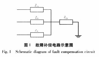
The impedance of the fault compensation circuit in Figure 1 is: 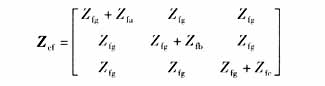
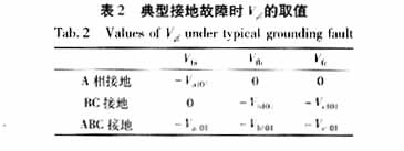
This allows you to simulate different faults by selecting the values ​​of Zfg, Zfa, Zfb, and Zfc. The values ​​of Zfg, Zfa, Zfb, and Zfc in several typical fault modes are shown in Table 1.

Wherein ALG indicates phase A single phase grounding; BCLL indicates BC phase phase short circuit; BCLG indicates BC phase indirect; ABCLL indicates three phase short circuit; ABCLG indicates three phase grounding.
2 Power flow fault calculation for weak ring network For weak ring networks, before the power flow fault calculation, the ring network should be torn to form a radial shape, the nodes are numbered, and the branches are layered. When numbering a node, the root node is first selected. The default root node number is 1. The numbering principle is: If a step needs to number m nodes, the new order of the m nodes is based on the next row they are connected to. The number of level nodes is determined. When the number of nodes of the next level connected by some nodes is the same, the new order of these nodes is determined according to their original order. Here, the method of the node number will be described with reference to FIG. Assume that node 1 has been numbered. As can be seen from the figure, nodes 2, 3, and 4 are connected to node 1, and now they are renumbered. It can be seen that the number of nodes in the next level connected to nodes 2, 3, and 4 is 1, 2, and 3, respectively, and the number of nodes 2, 3, and 4 in the new order is 2, 3, 4 (here) The new order is the same as the original order because Figure 2 is a network diagram that has been completed according to the numbering principle). After completing the node numbers 2, 3, and 4, the number of all nodes in Figure 2 can be completed in the same way. For the stratification of the branch, after the node number is completed, the branches are sorted according to the size of the nodes at both ends of the branch, and the number and layer of the branches are performed according to the principle of priority of the small nodes. Figure 2 is a completed new network diagram (only the node number is marked here).

2. 1 Radiating network power flow calculation Firstly, the amplitude and phase angle of each node voltage in the network are initialized with the amplitude and phase angle of the root node voltage. The iterative method for solving the radiant network power flow each iteration consists of 4 steps, and at the kth iteration:
(a) Node injection current calculation. Calculate the injection current of each node starting from the root node: 
Here, Ii is a column vector composed of three-phase injection current of node i; Vi is a column vector composed of three-phase voltage of node i; Si is a column vector composed of three-phase injection power of node i; Yi is all of node i Admittance of the grounding branch.
(b) Push back the branch current. Push back from the end of each feeder to the root of the feeder, calculate the current of each branch, and calculate the current of branch l as: 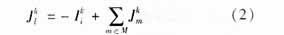
Here Jl is a column vector composed of three-phase currents of one branch. M means that all are connected to node i, except for the branch of branch 1.
(c) Previous generation operations. The node voltage is updated layer by layer from the root node to the end of the feeder. In the case where the voltage of the node i is known, assuming that the node j is connected to the node i through the branch l, the calculation formula of the voltage of the node j is: 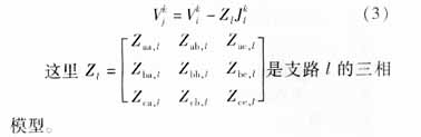
(d) Repeat (a) to (c) above until the voltage correction of each node's voltage in two consecutive iterations is less than a certain threshold.
The above (1) to (3) provide a formula for solving the three-phase current of the radiation network, but the effect of the ring network and the fault is not considered.
2.2 Compensation of ring network loop and fault loop 2.2.1 Unified calculation of loop loop and non-ground fault When there are loop loops and non-ground faults in the system, there are two loops in the system. The ring network loop in the power network; the other is the fault loop formed by the fault compensation circuit, the ground, the feeder root power and the feeder. As shown in Figure 3.
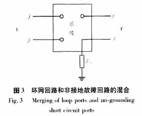
In Figure 3, L, F represents the ring network and the fault loop; j1, j2 are the nodes generated by the ring tear; f1 is a node in the system, and f2 occurs only when a non-ground fault occurs. Obviously, the ring loop and the non-ground fault loop can be regarded as two ports. The port injection current can be calculated according to the following formula: 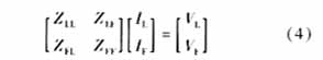
Among them, ZLL is the port impedance matrix of L, ZFF is the port impedance matrix of F, ZLF is the mutual impedance between L and F, and they are 3×3 matrix for three-phase calculation. The method for solving these matrices can be found in the literature [6, 7], and will not be repeated here. IL, IF are equivalent injection currents. 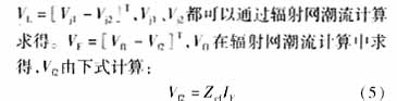
2.2.2 Calculation of ground fault The calculation of ground fault is based on the superposition principle. The ground fault is regarded as a sudden superposition of an additional injection current at the fault point under normal operating conditions, and the voltage and branch current of each node can be calculated after a previous generation pushback calculation. This additional current is calculated by: 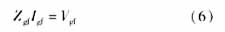
Where Igf is the additional injection current. Here Zgf can still be called the port impedance matrix. Its solution method is no different from the previous method of solving the port impedance matrix. It is not the same as other documents, because the Zgf is different. This is because the distinction between fault types has been implied in Zgf formed in this paper. Vgf=[Vfa Vfb Vfc]T, and the values ​​under several typical faults are shown in Table 1. If there are multiple faults at the same time, it is only necessary to extend Zgf and Vgf accordingly, without increasing the complexity of the program. Va|0|, Vb|0|, Vc|0| is the voltage at the fault point before the fault.
3 Compensation for PV nodes PV nodes in the distribution network are those nodes that can maintain the voltage amplitude at a certain level by adjusting the reactive power in the distribution network, such as reactive power compensation nodes existing in the distribution network. . The processing method for such a node is: if the calculation of the weak ring network power fault has converged, if the voltage amplitude of the obtained PV node is not equal to the set voltage amplitude, it is necessary to inject a certain size into the PV node, etc. Injects current, which allows the voltage amplitude of the PV node to reach a preset value.
In order to obtain an equivalent injection current, the voltage imbalance of the PV node is first required. In the calculation of the three-phase power flow fault, the three-phase equivalent injection current is taken into account, but for the PV node, the predetermined amplitude of the voltage is often given, and the three-phase is not distinguished, so the PV node is calculated here. When considering the voltage imbalance, only one phase is considered. The calculation formula is: 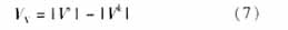
The VV is the voltage unbalanced column vector of the PV node, the dimension is equal to the number of PV nodes, Vs is the set value of the PV node voltage amplitude, and Vk is the magnitude of the voltage calculated by the power flow fault.
The second is to request an equivalent injection current. The PV node sensitivity matrix ZV is introduced here to calculate the equivalent injection current. The calculation formula is: 
Where ZV is a constant real number matrix. Its diagonal element Zii is the sum of the positive sequence reactances of all the branches connected from node i to the root node. When the PV nodes i, j have no common branch to the root node, the off-diagonal element Zij in the ZV is zero; otherwise Zij is equal to the positive sequence of the branch of the common part of the two roads formed by the node i, j to the root node The sum of the reactances. Here Iq is a linear approximation of the equivalent injection current. The actual injection current can be calculated using equation (9): 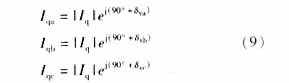
Here δva, δvb, δvc are the phase angles of the three-phase voltage of the PV node.
The case of reactive power limitation was not considered when calculating the equivalent injection current above. In general, since the PV node adjustable reactive power is not unlimited, it is necessary to calculate the reactive power in the case of additional injection current, and this reactive power cannot be exceeded. The calculation formula is: 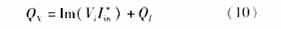

If the power is out of limits, then the PV node must be converted to a PQ node, and the ZV must be reformed and decomposed.
According to the foregoing, a calculation flow chart of the entire algorithm can be obtained, as shown in FIG.
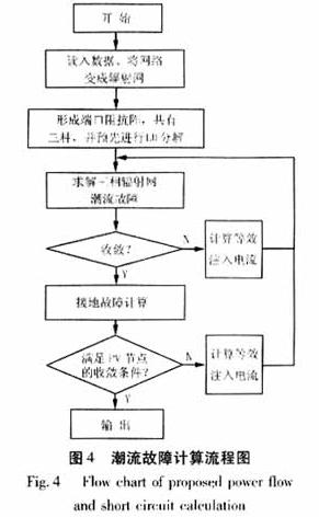
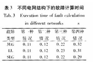
4 Example analysis Using the method of this paper, the typical system in PG&E is simulated. The system consists of a 21KV root node and two main feeders, a radiating net. By opening and closing the switches at different positions to simulate the change in the structure of the distribution network and the number of rings. Three faults are considered in the calculation: three-phase short-circuit grounding (3LG), phase-to-phase short-circuit (LL), single-phase grounding (SLG); four cases: in the first case, there is no PV node and ring network, in the second case There are 4 ring networks without PV nodes, in the third case there are 10 PV nodes without rings, and in the fourth case there are 10 PV nodes and 4 ring networks.
5 Conclusion Based on the calculation method of three-phase unified power flow faults in distribution network, this paper proposes a unified calculation of tidal current and non-ground faults for the deficiencies and defects of this method, and the ground faults are calculated according to the superposition principle. This method has the same convergence as the power flow calculation of the weak ring network. On this basis, the processing method of PV nodes is given. From the processing method, the processing method of unified calculation of power flow faults is very similar, and it does not increase the difficulty of programming, and it also meets the existence of the current distribution network. The phenomenon of work compensation.
The fan is made of high quality imported materials, high strength and high toughness, anti oxidation and corrosion resistance.
Scientific and reasonable fan shape design, to maximize the air volume and reduce the air flow and noise.
It uses high quality hydraulic bearing, to extend the service life, mute effect is also more excellent.
Water Cooling Fan meet the needs of different players, bring dazzling colorful visual effect.
Water Cooling Fan
Water Cooling Fan,Laptop Cooling Fan,Cooling Tower Fan,Cooling Fan Motors
Dongyuan Syscooling Technology Co., Ltd. , http://www.syscooling.com