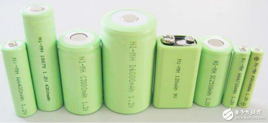
The structure of the single-metal nickel-hydrogen battery is sealed cylindrical with a nominal voltage of 1.2V. It has the following main features:
The "energy storage density" of the NiMH battery is exemplified by the No. 5 (AA type) rechargeable battery, which is at least 1000 mAh, and can reach 1400 mAh. Under the same volume and weight, the capacity is nickel-cadmium battery. ~3 times, and more than double the traditional nickel-cadmium battery.
"Memory effect" means that the battery is charged during the use of the battery because it is not completely discharged, causing abnormal oxides on the battery negative plate. It suppresses the battery voltage, which means that the battery is fully charged, but the discharge When the voltage is suddenly reduced, the battery life is shortened. Nickel-metal hydride batteries have no "memory effect", but there is self-discharge during use. Under normal use, the amount of electricity lost is 1% to 3% per day. Fully charged NiMH batteries, after being placed for a few weeks, must be recharged. Since the nickel-hydrogen battery has no "memory effect", it does not need to be discharged before it is charged, and it can be charged at any point with the charge.
Nickel-metal hydride batteries are more convenient to charge and discharge. Even if they are overcharged, they will not cause permanent damage to the battery. After the battery is discharged to 0V and then recharged, the capacity of the Ni-MH battery can still be restored.
Nickel-metal hydride batteries are also called environmentally friendly batteries or “green batteries†because they contain very little cadmium or even cadmium-free components and do not pollute the environment. Many countries have invested heavily in the construction of nickel-hydrogen battery production lines.
The hydrogen storage alloy used in nickel-hydrogen batteries is extracted from rare earths, and China is a large country with rare earth resources, accounting for about 80% of the total global storage. Therefore, the development of nickel-hydrogen batteries in China has unique advantages.
Ni-MH battery is charged with 1C current, the service life of discharge cycle is more than 500 times, and the service life of charge and discharge cycle is more than 1000 times with 0.2C current. From the actual service life, take the No. 5 Ni-MH battery as an example, charge with 1000mA current. Can be used repeatedly for 1000h.
NiMH battery charger design (1)The battery box is composed of 14 1.2V/1.8A·h nickel-hydrogen batteries, and each group is connected in parallel to form a 8.4V/3.6A·h battery. Each group of batteries is connected by current and over-temperature protection components, and is composed of a thermistor and a charging control board. It is connected to an external power adapter through a six-pin socket to realize charging control of the battery pack. Its circuit is shown in the figure.
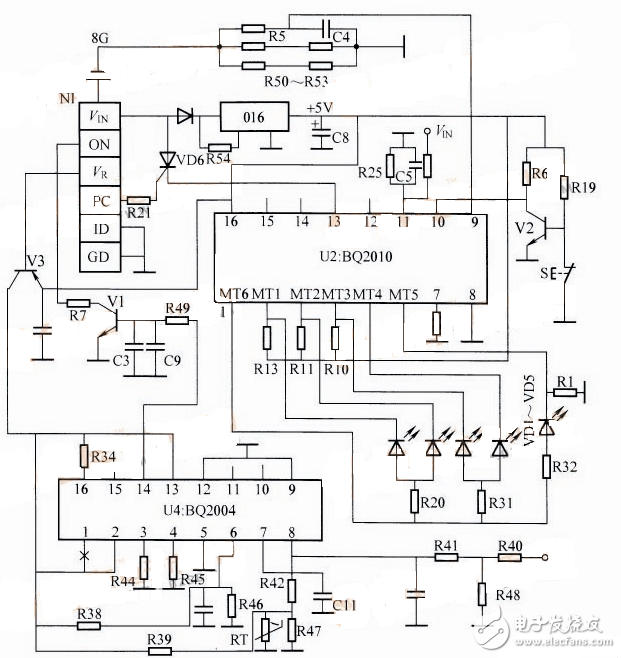
Circuit working principle: The charging control board consisting of bq2004/20lO can check the battery status at any time by detecting the button S and the five indicator lights, and timely charging to protect the battery pack from over-discharging.
U2 is the monitoring IC, the battery voltage is regulated by the five-terminal regulator 016, and +5V is used for U2. S is the break detection button, press S, V2 is turned on, 10 feet output low level, 1 foot MT6 output high level, according to different capacity of battery, corresponding MT1 ~ MT5 output low level, corresponding to light-emitting diode VD1 ~ VD5 Glowing. Pin 9 is the charging current detection input. Pin 11 is the battery voltage input terminal. The 13th pin is the charge and discharge control, and the battery is charged and discharged with the external DC terminal, and the high level is effective.
U4 (bq2004) is the charging control chip. When VR is low, V3 is turned on, U4 is powered to start timing, and the 14th pin charging control terminal outputs high level to make V1 turn on. The ON terminal low level controls external circuit to charge the battery. The seventh leg is the battery temperature detection input terminal, and the external temperature is closely attached to the negative temperature coefficient resistor on the battery to form a temperature sensor. Pin 5 is the battery voltage input.
The charging control board can control the charging of the battery from three aspects of time, battery temperature and voltage to achieve full self-stop.
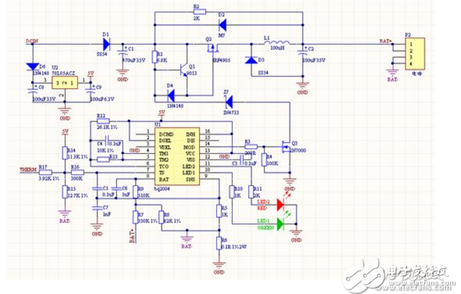
NiMH battery charger design (2)Circuit principle: Using bq2004 to build a nickel-hydrogen battery fast charging circuit, charging 10 nickel-metal hydride batteries, the maximum charge current is 2.25A, the circuit is as shown. After the circuit begins to charge the battery quickly, it quickly jumps to a full state (regardless of whether the battery is fully charged). The fast charging mode has a short duration and does not exceed the blocking time; the thermistor part of the circuit is connected to the 6.2K constant value resistor, which can guarantee the fast charging termination caused by any time; the circuit is designed according to the circuit of DV2004S1, there is no MTP23P06V This PMOSFET replaces the 2N7000 with the N tube of the AO4606.
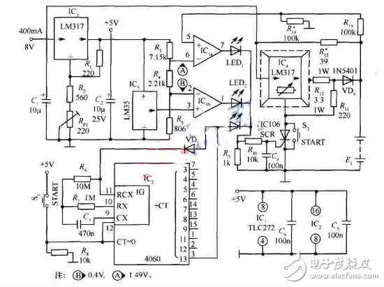
The self-made charger uses the four operational amplifiers of the LM324 as comparators. The voltage reference is set with TL431, and the S8550 is used as the adjustment tube to step down the input voltage and charge the battery. The principle circuit is shown in the figure. Its characteristics are simple circuit, reliable operation, no adjustment, easy to purchase components, etc. The following sections are introduced.
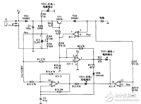
The external power supply is filtered by capacitor C1 after socket X and diode VD1. VD1 protects the TL431 from reverse polarity when the external power supply is reversed. R3, R4, R5 and TL431 form the reference voltage Vref. According to the parameter Vref=2.5&TImes;(100+820)/820=2.80(v), this data is mainly designed for Ni-MH rechargeable batteries (single-cell NiMH) The charged battery is fully charged with a voltage of approximately 1.40V).
2. High current charging(1) Working principle
When the power is turned on, the power indicator LED (VD2) lights up. Insert the battery (refer to the picture, actually lead to the battery box, the battery is installed in the battery box), when the battery voltage is lower than Vref, IC1-1 output low level, VT1 is turned on, output large current to the battery Charging. At this time, VT1 is in an amplified state - this is because the sum of the battery voltage and the -VD4 voltage drop is about 3.2V (assuming that the battery voltage is about 2.5V when charging starts), and the voltage after VD1 is about 5.OV, so VT1 The emitter-collector voltage difference is much larger than 0.2V. When the charging current is 300mA, VT1 heat is more serious. Therefore, it is better to use S8550 with PT=625mW, or increase the base resistance to reduce the charging current. Because the LM324 low-level drive capability is small, the measured IC1-2, IC1-4 output low level is not 0V, but is about 0.8V).
(2) indication of charging
First look at the operation of IC1-3: its non-inverting terminal 1O pin is connected to Vref through R13, R14 is connected to positive feedback, and the inverting terminal 9 is externally connected to the capacitor, and has a negative feedback path. Therefore, it actually constitutes a hysteresis comparator. At the beginning, there is no voltage at the upper end of C2, and IC1-3 outputs a high level. This high level has two discharge paths, one path is fed back to pin 10 through R14, and the other path is charged to capacitor C2 via resistor R15. When the charging voltage is higher than 10 pin voltage V+, the comparator flips output low. At the same time, due to the feedback effect of R14, the 10-pin voltage immediately jumps to V-. At this time, the capacitor C2 is discharged through the resistor R15. When the discharge voltage is less than the 10-pin voltage V-, the comparator flips the output again. Level, due to the feedback effect of R14, the 10-pin voltage immediately jumps to V+, after which the circuit repeats the above process. Therefore, the output of IC1-3 is a square wave signal with a fixed frequency.
Secondly, look at the working condition of IC1-4: the battery voltage is divided by R2 and R16, and connected to 12 feet of IC1-4. Because R2 "R16, the voltage of pin 12 of input IC1-4 is basically lower than the battery voltage.
Obviously it is lower than its l3 pin voltage, so the IC1-4 output is stable low. Combined with the above discussion, we can see that the R12 and VD3 paths are fixed at a fixed square wave voltage and the other end is a stable low level. Therefore, the LED VD3 will periodically illuminate, giving a flash The feeling of flashing.
Finally, look at the working condition of IC1-1: When IC1-2 outputs low level, it is obvious that pin 3 of IC1-1 is low level, and its 2 pin is connected to Vref through R1, so IC1-1 also outputs low level. Combined with the above discussion, we can see that the voltage difference between R11 and VD5 is zero, so VD5 (saturation indication) can not be lit!
In addition, since IC1-1 outputs a low level, no matter how the voltage of pin 9 of IC1-3 changes (capacitor charge and discharge form a triangular wave voltage at this pin), it will not be affected by IC1-1 output - because IC1-3 9 The pin voltage (either high to V+ or low to V-) is always higher than the output of IC1-1, and VD6 is reverse biased! Therefore, in this state, the operation of the three indicators is: VD2 is lit, indicating that the power is normal; VD3 is flashing, indicating that the battery is charging normally; VD5 is not lit.
3. Small current chargingWhen the battery voltage gradually rises to near Vref after charging for a period of time, the output voltage of IC1-2 rises slowly, so the current flowing through R7 gradually decreases, that is, the current flowing through the base of VT1 gradually decreases. Therefore, the current output of VT1 will gradually decrease, but the battery voltage will continue to rise slowly. When the battery voltage is almost equal to Vref, IC1-2 will output a higher voltage. At this time, IC1-1's 3-pin voltage is high. At 2.8 OV (inverting terminal 2 pin input voltage), the comparator flips the output high. This voltage has two functions: on the one hand, VD5 forward bias is turned on (at this time, IC1-4 output is still low), indicating charge saturation; on the other hand, VD6 is also positively turned on, and R17 is very Small, actually, the upper end of C2 is forced to be high level, so the voltage of pin 9 of IC1-3 is higher than the voltage of 10 pin, IC1-3 is forced to output low level, and VD3 is extinguished because there is no positive bias.
Although, from the external performance, the charging lamp is extinguished, the saturation lamp is turned on at a certain moment, but the charging process is gradually transitioning: when the battery voltage is much lower than Vref, the current is continuously charged, when the battery is charged. When the voltage is close, the charging current is slowly reduced until the charging gradually approaches zero - even if the saturation lamp is lit, the small current charging continues! Therefore, in this state, the working conditions of the three indicators are: VD2 is lit, indicating that the power is normal; VD3 is not lit; VD5 is lit (saturation indication, small current charging).
The charging circuit generates a temperature rise, especially when the charging circuit and the rechargeable battery are heated up at a high current. The LTC4060 external thermistor can detect the charging temperature to avoid overheating. The LT4060 has a temperature-controlled 2A NiMH battery charger as shown.
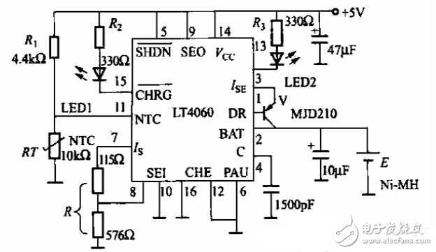
RT and LT4060 internal circuit constitute temperature detection circuit, RT is a negative temperature coefficient thermistor, you can choose a thermistor with a resistance of lOkn at 45 °C, close to the surface of the battery. When the temperature is high, the LT4060 will automatically reduce the charging current. When the temperature rises to 55 °C, the charging will stop automatically.
LED1 is the charging indicator and LED2 is the "charge full" indicator. 7 feet set the maximum charging current, III. =1395/R, 8 feet set the maximum charging voltage. The LT4060 has a charging current of o_4—2A and a supply voltage range of 4.5N10V. It can charge nickel-metal hydride and nickel-cadmium rechargeable batteries.
Android is an open source mobile operating system based on Linux platform released by Google at the end of 2007, and then improved for use in netbooks and MIDs. The platform consists of operating system, user interface and application software, and is claimed to be the first truly open and complete mobile software for mobile terminals.
To put it simply, the Android system is actually a very open system. It can not only realize the functions of the most commonly used notebook computers, but also realize various directional operations like mobile phones. Moreover, it is specially designed for mobile phones. The operating system developed for equipment has advantages in system resource consumption and human-computer interaction design. It is an operating system that combines traditional and advanced advantages.
New Android Tablet,Android Tablet,New Android Tablet
Jingjiang Gisen Technology Co.,Ltd , https://www.jsgisengroup.com