One of the most important things we have in car electronics is the potential path analysis. If you search for this word, you will rarely find it on the Internet. In fact, only aerospace military workers pay attention to it in China. Originally originated from the Boeing Company's completion of the Apollo mission to the moon, it was proposed for the electrical and electronic systems in space equipment. Boeing found that many faults and accidents were not caused by component failures. But caused by unintended states in the system design. Under these conditions, the system has circuit loops that some designers do not recognize, passing some kind of energy flow and information flow or control signal flow to varying degrees. Once the relevant parts of the system are excited by these undercurrents, they will produce unexpected functions or suppress the expected functions and cause system failure.
This article refers to the address: http://
If you want to understand this in depth, you can find some articles to look at and provide an introductory article: Potential Path Analysis Technology
We are discussing now that there are some differences between the potential path analysis in aerospace technology. We consider the car after the fuse is removed during the transportation or in the warehouse. (If you do not remove the fuse, the static current is a very troublesome thing. The battery will be in a state of no voltage for a long time, and the damage to the battery is very considerable. You can see the blog post: car quiescent current)
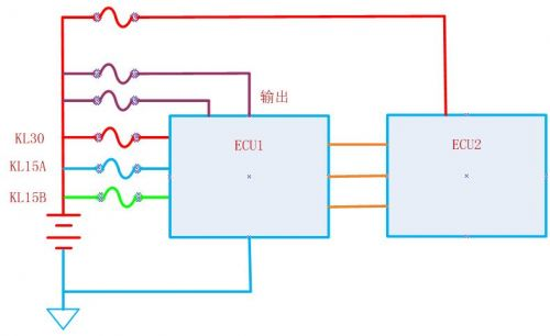
For our modules, we have a lot of power lines and load input lines. Since they come out from different fuses, we can't take all the fuses out of the fuse, so some of the load or the power is turned on. The main power supply BATT is definitely not feasible. What we need to do is to judge whether our module will have an abnormal state, and the external load will supply power to the power supply through the potential path or cause the module to be damaged.
Standard potential path analysis method:
1. Boeing's specification SCA method
Network tree generation tools and dedicated thread tables. Strictly follow the following six steps: data collection, system partitioning, data entry, path tracking, network tree mapping and analysis.
2. The simplified SCA method of the European Space Agency
Latent path analysis searches for all paths between the "source point" and the "target point" - and applies two types of clues to identify potential problems.
3. SoHaR's potential circuit analysis system SCAT
A so-called 'bidirectional path' that allows two-way current flow in the same circuit branch is searched.
For the methods in the car, the method we use is:
Please note that our most critical analysis is: to ensure that by analysis, if the fuse of the main power supply is disconnected, any other fuse circuit will not be able to supply power to the circuit.
I am here to mention one thing. Many manufacturers hope to use the KL30A (IGN1) and KL30 dual-channel power supply. If you encounter such a design, then jump here and the manufacturer defines the highest priority (you can't object to your customers)
The specific process is as follows:
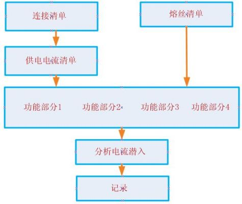
The first thing to do is to list the ECU we want to analyze, and all the other modules and components it connects to. Analyze the connections of all modules, components and ECUs in this list to determine if it is possible to provide current to the modules we are analyzing. Remove modules and components that cannot supply current from the list.
The second thing is to list the fuse and fuse connections involved in all the ECUs we analyze in the form of a list through the system block diagram of the module.
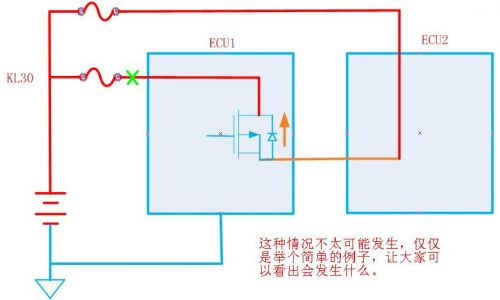
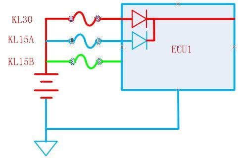
Then for each part, the next step is a detailed schematic connection, which lists all the connections in the form of functional units. Starting from a functional part, disconnect the main power supply of the ECU, and then analyze what happens. If there is an undercurrent flow path, record the fuse and components, and analyze all the branches to continue the next functional module.
The final results are evaluated and archived.
EO2 is an Ethernet extender over UTP cable. One EO2 at the network end can support one or multi remote models and their connected IP network devices. This EO2 can transmit over telephone line, Ethernet cable, and twisted pair. It is provided with excellent lightning protection and anti-interference capacity. In the real work environment, the network bandwidth could reach up to 60Mbps. With the Ethernet extended to 750meter, it has enlarged the Ethernet network application area, cutting down the project cost by using Cat5e or Cat6 cable.
N-net EO2 series have POE function, powering remote EO2 transceivers and their connected IP network device, default as a master terminal.
Ethernet And Power Over UTP Cable Converter
Ethernet And Power Over UTP Cable Converter,Power Over Ethernet,UTP Cable Converter,POE over UTP Cable Extender
Shenzhen N-net Technology Co.,Ltd , http://www.nnetswitch.com