When testing hardware circuits in peacetime, we often encounter problems that are easy to ignore and not easy to detect, but we must face up to these problems and try to weaken or eliminate them. This is called trap in hardware circuit measurement. .
When measuring voltage or current with a multimeter, the multimeter is connected in parallel or in series as a load and measurement object. If the load size of the measurement object is equal to the equivalent load of the multimeter, if it is of the same order of magnitude, the multimeter load must have an influence on the measurement object. For example, if the measured voltage is 10K, then if the equivalent load of the multimeter used is also of this order of magnitude, the result of the test must have a large error. According to the shunt theory in the parallel circuit, if you want to reduce this error, you must choose a multimeter with a large equivalent load, and the bigger the better. In general, when measuring a voltage, a pointer multimeter has an equivalent load distributed on the order of several tens of kilo ohms to several hundred kilo ohms depending on the range. When a digital multimeter measures voltage, it uses an active circuit as its Equivalent load, so its value is generally distributed in the order of magnitude of megaohms to ten mega-ohms according to the range. Relatively speaking, its influence on the measured object is much smaller, and the reliability of the test results is also higher. However, if the digital multimeter is regarded as a voltage sensor, its high-resistance equivalent load will easily pick up some noise voltage, so some test errors will be introduced. If this high-resistance probe effect is to be reduced. It is necessary to keep the test leads and the body as far as possible from some potential sources of noise interference during the measurement. The contradiction is once again reflected here.
From the point of view of the connection, the measuring instrument as the equivalent load actually participates in the work of the measured circuit. If the influence is to be considered, once the measuring instrument is involved in the test circuit, the working state of the whole circuit changes. If the influence of the measuring instrument on the circuit is relatively small, then the influence of the measuring instrument is a perturbation, which can be neglected. If the measuring instrument has a large influence on the circuit, the influence of the measuring instrument is an impact on the circuit system. This is why, sometimes when we do the test, once the test pen is placed on the test object, we see that the test object is self-excited, or it is not working, or there is a reason for the inexplicable noise. At this time, we need to do It is to replace the instrument with a small load effect or a test probe.
When measuring the AC signal with a multimeter, you need to pay attention to the working frequency of the measuring object. When the multimeter is used as the load to participate in the measurement, if you simply look at the meter from the meter to the multimeter, you can think that the multimeter is a filter because its measuring circuit is nothing more than A measuring circuit consisting of resistors, capacitors, and transistors. This circuit must have an operating frequency range (bandwidth). If it is measured within this frequency range, the test result is valid. If it is measured outside this frequency range, the test result will be Not accurate. Therefore, we must pay attention to the frequency range of the test instrument. This is the filter effect of the multimeter.
Similarly, when using an oscilloscope, AC millivoltmeter, UHF microvoltmeter and spectrum analyzer, you must also pay attention to the corresponding load effect and filter effect. The corresponding instrument should be selected according to the load and operating frequency of the tested object. In the instrument manual, there is generally a description of the size of the equivalent load, as well as a description of the operating frequency, which is more common and very easy to understand.
In general, when measuring low-frequency AC signals, if you want to measure the size of the signal, you can select the digital multimeter. If you want to see the time domain waveform of the signal, select the oscilloscope. If the signal is very weak, you can choose a millivoltmeter to work with the oscilloscope. When measuring audio signals, depending on the size of the signal, you can select an oscilloscope or millivoltmeter, an AC signal of the order of mV, which can be used with an oscilloscope and a millivoltmeter. For high frequency signals, an ultra high frequency millivoltmeter or spectrum analyzer can be selected. When using these instruments, you must pay attention to load effects and filter effects. Especially when measuring high-frequency small-signal (uV-order) circuits, if the load of the high-frequency amplifier is a parallel resonant circuit, if the spectrum analyzer (50 ohm load effect) is used for measurement, it will inevitably lead to a 50 ohm spectrum analyzer and parallel resonance. The circuit acts together as the load of the high-frequency amplifier, which inevitably leads to a decrease in the gain of the amplifier. The result of the test must be inaccurate. At this time, a differential high-impedance probe can be used with the spectrum analyzer for measurement, which can greatly reduce the load effect. Impact.
In addition, when testing crystals, it is common to use an oscilloscope for timing measurements, and also to test whether the crystal oscillates. At this time, we must pay attention to the load effect of the oscilloscope probe, because there will be parasitic capacitance on the probe, which is relatively small, generally pF magnitude, but the load capacitance of the crystal is generally also pF magnitude, so the intervention of the probe will cause the crystal oscillation circuit. The offset of the frequency, which affects the operation of the crystal oscillator circuit, can cause the crystal circuit to fail to oscillate. At this time, you must select a differential high-impedance probe for measurement.
Test the filter effect and load effect of the wire
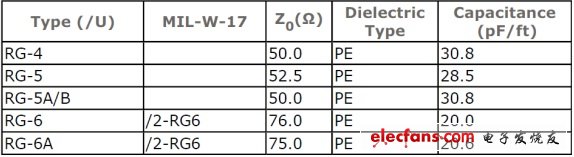
Generally, when measuring high-frequency circuits, we usually use RF coaxial lines, such as the common RG-58C. Intuitively, the 50 ohm RF coaxial line will not have too much impact on the measurement, but if it is actually Thinking, the transmission line can be regarded as a network composed of a series of LCRGs. Due to the existence of CL, there must be a working frequency range in this network. Due to the existence of RG, there must be loss in this network, so the transmission line will have a filter effect on the test system. That is to say, the transmission line also has a problem of operating frequency range. If we use a network analyzer to test an RF coaxial line such as RG-58C and scan its S21 over a wide frequency range, we will find that this coaxial line is A low-pass filter, from the non-ideality of the RF wire, this measurement should be expected. It is conceivable that if we simply let this coaxial line work far away from its low-pass filter corner-frequency, then from the perspective of RF matching, this coaxial line is not a 50ohm or 75ohm match. The axis, if used, will inevitably cause a large amount of reflection loss, and it is necessary to reselect other RF wires. The following table is a parameter table of the RF coaxial line. It can be seen that the equivalent capacitance is about 20~30pF for each length of the coupon. For high frequencies, this is a relatively large capacitor, which is why we When making RF measurements, you must choose the reason why the coaxial line is as short as possible.
Correspondingly, when measuring high-frequency signals (or high-frequency digital signals), the equivalent load effect of the ground wire of the oscilloscope probe must also be considered. The intervention of the probe ground wire changes the characteristics of the test system, and the probe ground wire acts as An inductive load component inevitably causes a change in the transmission characteristics of the test object, causing a change in the test result, which seriously causes system oscillation and self-excitation.
The above is the filter effect and load effect of the test wire.
If we understand the pitfalls in these test systems from the perspective of basic circuit theory and signal and system, we can easily understand and understand how to reduce and eliminate the effects of these problems when selecting instruments or tests.
Spin dryers are very common in every family. Banshen spin dryers, with high quality, good design and best service. Many products have been sold to over 30 countries. After many years of developing, banshen spin dryers are getting better and better.
Our well-equipped facilities and excellent quality control throughout all stages of production enable us to guarantee total customer satisfaction. Besides, we have received CE, CB, RoHS and CCC certifications.
As a result of our high quality products and outstanding customer service, we have gained a global sales network reaching America, Asia, Europe, Africa, the Middle East and other countries and regions.
If you are interested in any of our products or would like to discuss a custom order, please feel free to contact us. We are looking forward to forming successful business relationships with new clients around the world in the near future.
Round Spin Dryer,Clothes Spin Dryer,Mini Clothes Dehydrator,Mini Transparent Spin Dryer
Ningbo Banshen Electric Appliance Co., Ltd , https://www.banshendq.com