SPC3 protocol chip
SPC3 is an intelligent communication chip dedicated to the development of slave stations, which supports the PROFIBUS-DP protocol. Figure 1 is the SPC3 structure diagram, its main performance is as follows: 44 feet, PQFP package; automatic detection of baud rate on PROFIBUS, from 9. 6kbps to 12Mbps; RS-485 transmission; complete PROFIBUS-DP protocol; internal integrated monitoring timing Device; 5V DC power supply.

Figure 1 SPC3 structure diagram
SPC3 internally integrates a 1.5KB dual-port RAM, and its address space ranges from 00H to 5FFH. The unit is divided into 192 segments with 8 bytes as a unit. According to the function, it can be divided into 3 areas:
00H to 015H are the mode setting and status indication register area. 016H to 03FH is the parameter configuration area, and the pointers and lengths of various BUFs are set in this area. 040H to 5FFH is the user area, used to receive data from IO applications and the master station. The configuration of these BUFs, including the length and initial address of the BUF, must be completed in the "offline" state of SPC3; during the operation, except for the length of the input and output BUFs, other configurations cannot be changed. In addition, a watchdog timer is integrated inside SPC3, which can work in 3 different states: baud rate monitoring, baud rate control and DP control.
TMS320F206
TMS320F206 is a 16-bit fixed-point DSP with an operation rate of 40MIPS. It is manufactured using a static CMOS integrated circuit process. Its structure is based on the 'C5x, with an improved Harvard structure. It has a program bus and 3 data buses, pipeline operations, parallel 32bit arithmetic logic units, and 16 × 16bit parallel hardware multiplication Memory, on-chip memory, on-chip peripherals, and highly specialized instruction sets. On-chip resources include: internal clock generator, which can be connected to a clock source for × 1, × 2, × 4, and / 2 to generate the CPU clock; there are RAM4.5KB and FLASH32KB on-chip, which can be suitable for many engineering applications, 32KB FLASH can be used as a program memory, which brings great convenience to system design and program debugging; 3 external interrupts INT1, INT2, INT; 1 synchronous serial port and an asynchronous serial port; 1 software programmable timer; 4 independently programmable I / O pins, 1 output pin XF and 1 input pin B IO; JTAG scanning simulation interface, used to realize online simulation testing.
Hardware system composition
Figure 2 shows the hardware block diagram of the PROFIBUS-DP slave station. The system consists of MAX125, TMS320F206, SPC3, EPM7128SQC100, DS1286, HK1225, external RAM and address dial switch to form a PROFIBUS-DP slave station for the diagnosis of railway signal power failure. The three-phase AC voltage and current signals are synchronously sampled by MAX125, and the DSP performs data processing and data calculation through a certain algorithm, and then synthesizes the relevant switching signal conditions to make a diagnosis and control the power equipment. At the same time, the necessary data and fault information will be transmitted to the master station through the protocol chip SPC3 according to the requirements of the PROFIBUS master station. The master station also sets the slave station and remotely controls the power equipment through SPC3.

Figure 2 hardware circuit diagram
The 8-bit SPC3 in the design uses the lower 8-bit data line of TMS320F206 and maps it to the global data space; it also maps the DS1286 and HK1225 digital inputs and digital outputs to the global data space. In this way, DSP operations on them are as simple as operating external RAM. When the 16-bit DSP in the program design writes to SPC3, DS1286, HK1225, write the lower 8 bits first and then the upper 8 bits.
System software implementation
PROFIBUS-DP slave station (that is, the terminal unit for fault diagnosis) mainly completes data collection, data processing, fault judgment, and transfers necessary electrical energy parameters and fault information to the master station according to the requirements of the master station. Assignment.
Design of SPC3 communication software
In the design, the electric energy parameter is regarded as the input data of the slave station, the assignment of the master station to the slave station is regarded as the output data, and the fault information is treated as external diagnosis. The processing of the assignment of the master station adopts the SPC3 interrupt method in order to achieve real-time. In addition, the processing of parameterized messages and configuration messages is also completed in the SPC3 interrupt program. SPC3 interrupt program flow chart shown in Figure 3.

Figure 3 SPC3 interrupt program flow chart
Because SPC3 integrates a complete DP protocol, standard diagnostic information is automatically formed and transmitted by SPC3, so the user can store the information communicated with the DP master station in the designated buffer; when the user needs to receive the information from the master station At the same time, only need to access the specified buffer.
The Design of Intelligent Software of TMS320F206
Data collection, data processing, fault judgment, and recording of necessary information are completed in the TMS320F206 program. In order to continuously monitor the system, the data collection uses an interrupted method to continuously collect data. For the fault information, the method of soft interrupt is adopted, and the fault alarm information is sent to the diagnostic buffer of SPC3 as soon as possible, so that it can wait for the polling of the master station in time. Figure 4 shows the main program flow chart of the system.
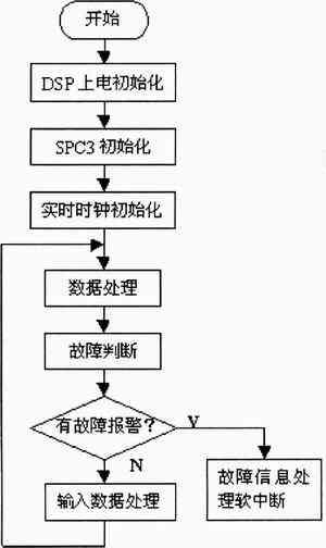
Figure 4 main program flow chart
SPC3 software operation
Due to the fast speed of TMS320F206, the speed must be the same when data exchange with SPC3. We set the waiting time of F206 through software to match the speed of the two. In the design, SPC3 adopts the structure type register method to operate it. First define a structure type data "SPC3" corresponding to the 1.5KB dual-port RAM, and then define a "SPC3" type register "spc3" in the header file of the F206 register, so that it can be easily and flexibly carried out Operated. The software is written in C language, and the initialization part of SPC3 is as follows:
The "spc3" register is defined in the header file
#define spc3 (* ((volaTIle SPC3) 0xE800))
/ * SPC3 maps to 0xE800 in the global data space * /
// Initialization operation:
GREG = GLOBAL 16K; / * Map to 16KB global data space * /
spc3. mode_ reg0_ L = 0x00d3;
spc3. mode _reg0 _H = 0x0003; / * Set the working mode of SPC3 * /
spc3. is reg. mask [0] = 0x001e;
spc3. is reg. mask [1] = 0x002d; / * Set SPC3 interrupt source, set output data processing as SPC3 hardware interrupt * /
spc3. r len diag buf [0] = 16;
spc3. r len diag buf [1] = 16;
spc3. r len p rm buf = 10;
spc3. r len cfg buf = 2;
spc3. r len read cfg buf = 2;
spc3. r len din buf = 244;
spc3. r len dout buf = 244; / * Initialize the length of each buffer / *
UserInputBufferPtr = DPS2 GET D IN BUF PTR (); // Get the address of the first input buffer
UserDiagBufferPtr = DPS2 GET D IAG BUF PTR (); // Get the address of the first diagnostic buffer
UserDiagFlag = TRUE;
...
In this paper, a 16-bit DSP with fast operation speed is used to design a PROF IBUS2DP intelligent slave station, which makes the field bus more widely used.
Plug-in fuses are designed to be inserted into the fuse box. Fuse is small safety part in an electrical device or piece of machinery that causes it to stop working if the electric current is too high, and so prevents fires or other dangers. Fuse in the abnormal current increases to a certain height and heat, its own fuse to cut off the current, to protect the safe operation of the circuit fuse protection power equipment with current overheating damage, avoid electronic equipment serious damage caused by internal fault. When a circuit breaks down or is abnormal, the current increases with the current and the increased current may damage some important components in the circuit, and it may also burn the circuit and even cause a fire. If correctly placed in the circuit fuse, the fuse will be abnormal current increases to a certain height and heat, its own fuse to cut off the current, so as to protect the safe operation of the circuit.
Auto Plug-In Fuses,Plug-In Style Fuses,Blade Fuse,Mini Auto Plug-In Fuse
Heshan Jianhao Lighting Industrial Co., Ltd. , https://www.sunclubtw.com