1 Introduction to the oscilloscope
This article refers to the address: http://
An oscilloscope is a tool used to measure fluctuations in voltage or current in a circuit. It can reflect the operation of the device in real time. In the circuit analysis pass. It is used to measure the waveform of the input and output, and the observer has analyzed and studied to obtain the excellent condition or problem of the performance of the circuit.
2 Importance of sensor waveform analysis in automotive fault diagnosis
With the development of modern automobile technology, a large number of sensors are used in automobiles, and when the sensor feels the change of physical quantity in its working environment, it transmits the sensed change to the automobile ECU by current or voltage, and the EZCU receives After the signal sent by the sensor, make a corresponding judgment, drive the relevant equipment to work, and adjust the working state of the car.
Sensors used in modern cars can be divided into: temperature, speed, pressure, oxygen content, vibration and position sensors, which generate a variety of voltage or current signals, which can be reflected in waveforms by an oscilloscope. come out. When the perceived physical quantity changes normally or abnormally, it can be reflected by the fluctuation of the waveform. By comparing with the normal waveform, the faulty part can be judged.
What is said here is not that the oscilloscope can solve all the problems in vehicle maintenance, but it provides a way to judge the fault, a means of dealing with the problem, just like the stethoscope used by doctors.
3 Case analysis
Trouble phenomenon A Volkswagen Passat 1.8T sedan, there is a phenomenon that is difficult to start, it is necessary to start the fire several times each time. The last time it is dead in the driving, it will not be able to fire, and can only be dragged to the 4S shop. service.
After the fault diagnosis to the store, it can be started at the same time and can not be started. The fault is detected by the 1552 diagnostic tool for the crankshaft position sensor. Then replace, restart, the fault phenomenon remains. Then change the camshaft position sensor and try again. The fault phenomenon is still there, and the maintenance is in a deadlock.
Fault analysis and test using a dual-track oscilloscope to simultaneously measure the waveform of the crankshaft position sensor and camshaft position sensor on the faulty vehicle. As shown in Figure 1, the camshaft position sensor and the crankshaft position sensor waveform measured on the same type of normal vehicle are shown in the figure. 2 is shown.
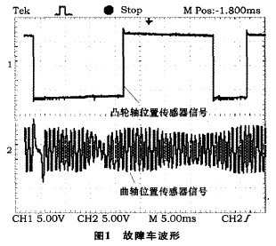
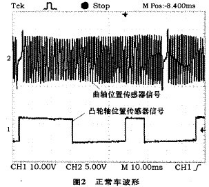
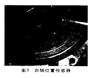
By comparing Fig. 1 and Fig. 2, it is found that the crankshaft position sensor waveform is different. Why is there such a difference, is it normal or not? After analyzing the structure of the crankshaft position sensor, it can be seen from the structure of the crankshaft position sensor of Fig. 3 that it is a ring of notched teeth. Comparing the waveform of the crankshaft position sensor in Fig. 2, it can be concluded that there are 60 gaps in the ring. The tooth, in which one notch occupies the position of two teeth, 59 sine waves can be calculated in the waveform of the crank position sensor in Fig. 2, corresponding to 59 notch teeth of the crank position sensor ring, and the camshaft position sensor in Fig. 2 The position with a large spacing in the waveform corresponds to the position of the two missing teeth of the notched ring. The waveform generated by the crankshaft position sensor has a starting position relationship with the camshaft position sensor waveform of Fig. 2. This relationship can be more clearly seen by Fig. 4.
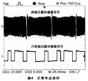
It can also be seen from Fig. 4 that the crankshaft position sensor waveform appears twice before the camshaft position sensor waveform coincides with the initial position. This relationship is consistent with the relationship between the crankshaft speed and the camshaft speed ratio of 2:1. It is the position of the top dead center of one cylinder, that is, the reference position of the ignition timing of one cylinder, and also determines the ignition timing of the other three cylinders. This signal is transmitted to the foot and the ECU can send an ignition signal to start the engine. Otherwise the ECU will not issue an ignition signal and the engine will not start.
Trouble shooting can not solve the problem after replacing the crank position sensor and the camshaft position sensor, so the idea is transferred to the notch ring of the crank position sensor, the waveform of the left third of the camshaft position sensor waveform in Fig. 1 and other The place is different, and it is different from the waveform of the normal car. The sensor is ok, there is only a problem with the notch ring of the crankshaft position sensor, and it is at a distance of 15 teeth from the large notch. At first, it was suspected that there was a foreign object on the 15th tooth, which caused the sensor signal to be bad. The sensor was installed and the foreign object could not be seen. Therefore, only the oil pan can be disassembled, and the oil pan can be disassembled and then transferred to the 15th notch position. As shown in Fig. 3, the notched ring of the position indicated by the iron bar is not a foreign object, but is slightly deformed. After the deformation, the distance between the position and the sensor becomes large, so that the generated signal is not strong enough to generate an abnormally small waveform. This car problem was completely solved after replacing the crankshaft.
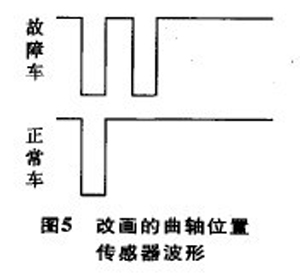
Summary of the fault Why is this car difficult to start intermittently? Let's look at the waveform of the crankshaft position sensor in Figure 1 and Figure 2. If a horizontal line is drawn at the bottom of the crankshaft position sensor waveform in Figure 1, the horizontal position of the crankshaft position sensor waveform is plotted in Figure 2. Line, according to the presence or absence of waveforms on this line can be derived from the two waveforms in Figure 5, the ECU can only send the ignition signal to start the engine when the waveform shown in Figure 5 is below, and the ECU obtains the waveform on Figure 5 and cannot issue the ignition signal to start the engine. However, the engine can be started when the waveform generated at the fault location happens to reach the acceptable bottom line. After starting, the ECU detects the crankshaft position sensor waveform less stringently, so it does not turn off after the engine is started. This is the root cause of this car failure.
Another tip: This fault reflects the engine's strict start and protects the engine; but when the engine is started, the design concept of the engine is maintained as much as possible.
4 Summary
The diagnosis of the vehicle fault fully utilizes the dual-track display function of the dual-track oscilloscope, so that the relationship between the waveform and the rotational speed of the crankshaft and the camshaft is clearly reflected, so that the judgment and positioning of the fault are relatively rapid.
Car Charger,Electric Car Battery Charger,Mini Car Charger
Double USB Travel Plug,Single Country Plug Adapter Co., Ltd. , http://www.chtravelplug.com