Abstract: With the increasing complexity of the electromagnetic environment in modern electronic warfare, military receivers need to have the ability to simultaneously process multiple channel signals, that is, have full probability interception capability. The channelized receiver divides a complex signal into multiple channels for subsequent processing. The simplified structure is used to verify the feasibility of this channelization scheme and save logic resources.
In electronic warfare, the swept-frequency search receiver is traditionally used, but its intercept probability is more affected by the search speed, and because it is constrained by the relationship between search speed and resolution, the swept receiver pair The interception effect of the frequency hopping signal is not ideal. A channelized receiver is a receiver that receives the full probability of a signal in a certain frequency band, and a channelized receiver based on a polyphase structure requires less hardware resources for the same frequency band signal than a conventional channelized receiver. And easier to implement. Compared with its traditional multi-phase structure, its relatively traditional channelized receiver has been widely used in multi-channel processing and is the development trend of receivers.
1 Channelization principle of polyphase filtering structure 1.1 Channel divisionSince the real signal spectrum has symmetrical characteristics, its frequency band division is special. Here, only the spectrum on [0, π] is channel-divided. If K channels are divided, the center frequency of each channel is ωk=kπ/K+π/2K, where k=0, 1, . . . , K-1.
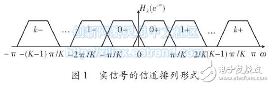
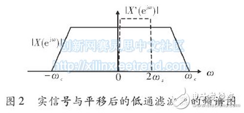
According to the Fourier transform, the spectrum of the low-pass filter includes two parts of positive and negative symmetry. In order to divide the channel as shown in Figure 1, all the spectrum of the filter function needs to be moved to the positive half axis. Here, the spectrum function of the filter is transformed as follows.
At this time, the frequency domain is reflected as shown in FIG. 2, and therefore, the input real signal is filtered by a complex FIR filter.
The main process of channelization is to multiply each channel first, then move the signal in the frequency domain, then pass the low-pass filter, filter out the high-frequency components, and reduce the frequency to the baseband, and then down-convert, and finally proceed. Extract. The channelization structure is shown in Figure 3.
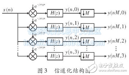
In the figure, ωk represents the center frequency of the kth channel, and H(z) represents a low pass filter. However, the problem is that after each channel's signal has been subjected to a series of calculations, it is extracted, and there will be more data calculation loss in the middle. Therefore, there is a need for a simplified method to make calculations more efficient.
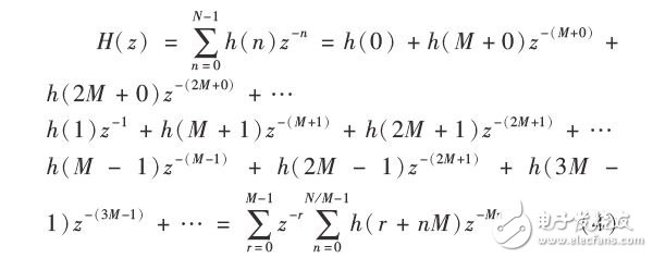
According to Figure 3
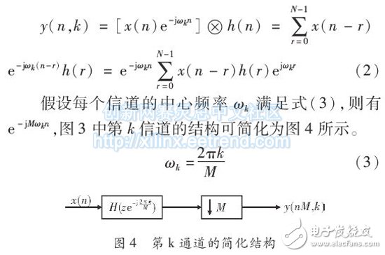
At this point, only the low-pass filtering and the decimation are left, and the Noble equivalent can be used again to simplify. For this reason, the FIR filter is transformed as follows.
According to the Noble equivalent, the extraction can be moved to the FIR filter as shown in Figure 5.
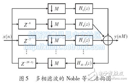
Referring to FIG. 5 and looking at the whole system, it is easy to find that x(n) can be regarded as entering the respective channels after serial-to-parallel conversion, that is, the data of the n=mM+k period of x(n) enters the kth channel for operation.
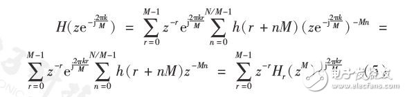
At this point, the structural simplification of polyphase filtering has been completed. Returning to the channelization scheme of this paper, according to equations (3) and 4, z is used instead, and equation (4) can be transformed as follows.
Then there is a final channelization efficient structure as shown in Figure 6, so that the output of each channel FIR filter is yr (nM), then the total output is
48V30Ah Lithium Ion Battery,Long Cycle Life 48V 30Ah Battery,48V 30Ah Battery For Vehicle,Deep Cycle Life Battery
Jiangsu Zhitai New Energy Technology Co.,Ltd , https://www.jszhitaienergy.com