With the development of computer and communication technology, the diversification and informationization of various PLC modules, the distributed control system with PLC as the basic control unit is widely used in the field of automation. There is an urgent need for a bus that can be suitable for long-distance digital communication. . Based on the RS422 standard, EIA has developed an RS485 bus standard that supports multi-node, long-range and high-sensitivity reception. EIA used to prefix all its standards with the RS prefix (English abbreviation for RcommendeStandard), so many engineers have used this name, because RS485's long distance (1200m), multi-node (32) and low transmission line cost make EIA RS485 has become the preferred standard for data transmission in industrial applications.
The commissioning line of 18 electric actuators in our factory is distributed in several areas of three workshops. Each debugging line is controlled by a PLC and HMI. In order to manage the debugging data and judge the correctness of the debugging results, the debugging line is carried out. Monitoring, 18 PLCs are connected with the computer through RS485 bus to form a distributed monitoring system. Through data communication, the computer and PLC realize data sharing, and complete centralized management and decentralized control of the debugging process. The communication between the computer and each sub-station of PLC is an important part of the system. This paper discusses in detail the RS485-based bus, develops the host computer communication system with VB, and writes the design and practical application scheme of the communication protocol of PLC free port. It can be used as an application example designed for various communication systems such as PC, PLC, HMI, etc. It can also be used as a platform for engineering project training and teaching in the fields of detection technology and automation design.
1RS485 network compositionThe RS485 standard uses balanced transmit and differential receive data transceivers to drive the bus. Like RS422, multiple (up to 32) RS485 interfaces can be interconnected, and the connection is simpler. The "+" end is connected to the "+" end, the "-" end is connected to the "-" end, and the two connected lines are the "physical bus" of RS485. The physical status of these interconnected RS485 interfaces is completely equal, with one logically dominant and the other subordinate. In the case of communication, the same method is used for the primary call and the secondary response.
The hardware structure of the control system is shown in Figure 1. The upper computer is a computer, and the lower computer uses Siemens S7-200 series PLC. Each PLC is directly connected to the RS485 bus through communication port 0. The upper computer passes RS232/485 converter and RS485. The bus is connected to form a 1:N communication mode. In the control system, the main task of the host computer is to obtain the data information on the debug line and complete the monitoring of the debugging process. The main task of the lower computer is to automatically control the debugging process, send the debugging data to the host computer, and execute it according to the host computer command.
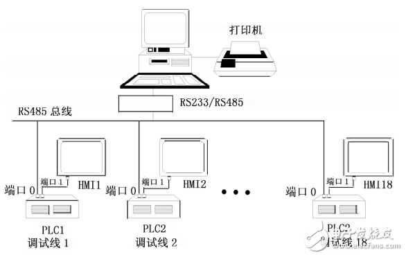
Figure 1 network diagram
2 computer and PLC communicationThe communication between the host computer and the PLC is actually the exchange of commands and responses between the communication module of the computer and the PLC. The lower computer has the initial transmission priority, and sends all the debugging data to the upper computer. The upper computer judges which debugging line according to the received data. The sent data, in response to the data analysis, returns the data and commands, and the lower computer only receives the data sent to itself. Communication is performed in units of "frames", which are divided into data frames and response frames. The data frame is sent by the PLC to the host computer; the response frame is the command and judgment signal automatically sent to the PLC after the host computer receives the data frame. All the command codes, characters and data are sent and received in hexadecimal code.
There are two communication modes of S7-200 series PLC: one is the point-to-point (PPI) communication protocol, which is used for communication between PLC and its programmer or Siemens human-machine interface products; the other is the freedom to open completely to users. Port mode (freeportmode), the protocol for communication by the user. PPI mode can only communicate in PLC stop mode (STOP), while free port mode can only communicate under PLC running mode (Run). We use free port communication mode to initialize the serial port before communicating. The initialization of the S7-200PLC is achieved by setting the special flag bit SMB30.
2.1 PLC send commandSend S7200 series PLC has a special send command for sending data in the format:
XMTTABLEPORT
XMTTABLEPORTTABLE is the number of bytes of data to be sent, that is, the length of the data, up to 255. The data to be sent must be stored after TABLE. If the storage area of ​​TABLE is VB600, the data storage form to send "MESSAGE" is shown in Figure 2. PORT specifies the communication port, this item is set to 0. When the data is being transmitted, the PLC special flag SM4.5 is 0; after the transmission, SM4.5 is 1. Therefore, post-transmission processing can be performed by judging the state of SM4.5.
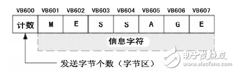
Figure 2 PLC sends information
If an interrupt service routine is connected to the transmit end event, an interrupt is generated when the last character in the buffer is sent (interrupt event 9 for port 0 and interrupt event 26 for port 1).
A buzzer or beeper is an audio signalling device, which may be mechanical, electromechanical, or piezoelectric (piezo for short). Typical uses of buzzers and beeper include alarm devices, timers, and confirmation of user input such as a mouse click or keystroke.
Piezo Buzzer,Dc Electro Magnetic Buzzer,Buzzer Acoustic Components,Piezo Buzzer For Thermometer
Jiangsu Huawha Electronices Co.,Ltd , https://www.hnbuzzer.com