Functionally, the electronic load is the exact opposite of the power supply, which is used to power electronic products, while the electronic load is used to absorb or consume power. However, in terms of working mode, the power supply and the electronic load are very similar, and usually work in a constant voltage CV mode or a constant current CC mode. In practical applications, the operating mode of the electronic load is usually opposite to that of the power supply. That is, the constant voltage CV source needs to use the electronic load of the constant current CC mode, and the constant current CC source uses the electronic load of the constant voltage CV mode. Of course, almost most electronic loads have another constant-resistance CR mode that is used to simulate real-world resistance-characteristic electronics. This article mainly introduces how the electronic load can realize the CV, CC or CR working mode, but it is recommended to read the previous article on how to realize the CV and CC mode output of the DC power supply. In fact, whether it is DC power or DC electronic load, the implementation principles of CC and CV working modes are very similar.
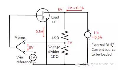
Figure 1 is a block diagram of the CC mode of the electronic load.

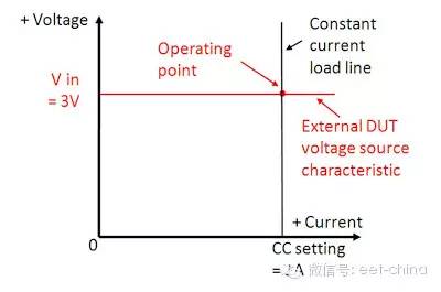
When an electronic load operates in CC mode, its power supply device is usually a voltage source. The current amplifier of the electronic load compares the voltage across the sense resistor R with the reference voltage and then controls the RDS of the FET field effect transistor so that the entire loop operates and remains at the set current. Figure 2 shows the corresponding IV curve in CC mode. The exact operating point is the intersection of the voltage of the voltage source and the current set by the electronic load.
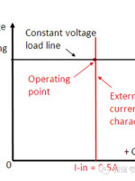
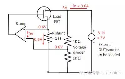
The CV mode is very similar to the CC, as shown in Figure 3. The difference is that the voltage on the current sensing resistor is no longer the voltage, but the voltage across the piezoelectric circuit. At this point, the voltage remains stable and the FET FET absorbs as much current as possible from the external source.
A common lithium battery is a typical CV source, and the battery charging process requires the use of a constant current source. Figure 4 shows the corresponding IV curve in CV mode.
The CV and CC modes are relatively close to the implementation of the DC power supply, and are relatively simple. How is the CR mode of the electronic load implemented? As shown in Figure 5, when the CC and CV modes are simultaneously controlled, the ratio of specific voltage and current (V/I = CR) is maintained, that is, the voltage and voltage loops on the current loop "sense resistance R" are compared. The voltage value on the resistor. For example, in this example, the current is 1V/A and the voltage is 0.2V/V, and the equivalent resistance R is 5Ω.
The electronic load in CR mode is commonly used in electronic devices that simulate the actual storage resistance characteristics and is used to test power supplies that can operate in either CV or CC mode. Figure 6 shows the corresponding IV curve in CR mode.

Through the above introduction, we also see that the electronic load is very similar in CV or CC operating mode control, but most of the electronic load can also simulate the load of pure resistance characteristics.
Suizhou simi intelligent technology development co., LTD , https://www.msmvape.com