If you're familiar with an oscilloscope, you might have wondered: why does it have input impedances of 1MΩ and 50Ω? How do you choose between them?
Let's start by understanding the concept of transmission lines. Electrical signals travel through cables as electromagnetic waves. When the length of the cable becomes comparable to the wavelength of the signal, wave behavior becomes important. For example, when a narrow pulse is sent through a 100-meter coaxial cable and terminated in a short circuit, the oscilloscope at the source will show both the incident and reflected waves.
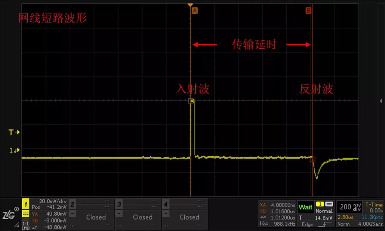
When these waves interfere, the square wave can become distorted, as shown below:
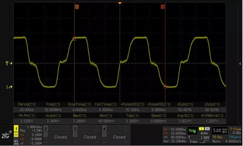
To prevent signal reflections, we use uniform transmission lines like PCB microstrips or coaxial cables. These maintain consistent geometry and material, reducing reflections. However, even with a uniform line, reflection can still occur at the end if the load doesn’t match the characteristic impedance.
Characteristic impedance is a key factor here. It’s purely resistive and depends on the structure and materials of the transmission line. To avoid reflections, we match the load impedance to the characteristic impedance—this is called termination matching.
Now, let's talk about the famous 50Ω. This value was chosen because it offers a good balance between power transfer, loss, and manufacturing cost for coaxial cables. As a result, 50Ω became the standard for high-speed systems like PCIe. That’s why oscilloscopes often have a 50Ω input mode—to match this system and minimize signal distortion.
But why is there also a 1MΩ setting? This comes down to the loading effect of the oscilloscope. When connected to a circuit, the oscilloscope’s input impedance (typically around 1MΩ with a small parallel capacitance) can affect the signal. At low frequencies, the resistance dominates, but at higher frequencies, the capacitance becomes more significant. This can cause measurement errors, especially if the circuit under test has a low output impedance.
For high-frequency measurements, using a 10:1 passive probe is better, as it has lower capacitance (around 9pF) compared to a 1MΩ probe (about 60pF). If even that isn't enough, an active probe with much lower parasitic capacitance may be needed.
What happens if you measure with 50Ω instead? Let's say the source has an output resistance of 25Ω. In this case, using 50Ω would cause significant signal attenuation, leading to distortion. So, 50Ω is only suitable when the signal is already matched to the transmission line, such as when using a 50Ω coaxial cable from a signal generator.
In summary, choosing between 1MΩ and 50Ω depends on the context:
1. Use 50Ω when measuring a no-load signal source with a 50Ω coaxial cable to prevent reflections.
2. Use 1MΩ when measuring onboard signals that already have proper termination.
3. Passive probes typically work best with 1MΩ, while high-frequency active probes may require 50Ω.
4. Be mindful of probe bandwidth—1:1 probes are limited to around 6MHz, so use attenuated probes for higher frequencies.
Bang 25000 Puffs Ehookah Oil Ecig Disposable Vape


Bang 25000 puffs Ehookah oil Ecig disposable vape
Shenzhen Yingyuan Technology Co.,ltd , https://www.yingyuanvape.com